March 2026
Volume 31 Number 3
Next meeting: 11:30AM March 21st at Round Table Pizza in Martel. Find out more.
Thirty Years Ago, a bunch of local hams gathered for pizza at Mountain Mike’s Round Table in Martel, and the Mother Lode DX/Contest Club was born!
In this issue: Missives from our new Prez and VP! –Solid state amps and a Tube of the Month – lotsa news – Monthly features! – bunches of state QSO parties – a look back 10 & 20 years – classifieds – DX – focus contests? – more funny stuff! – and more!
2026 Meeting Dates
- March 21
- April – none
- May 16
- June 20
- July 25
- Aug 22
- Sept 19
- Oct 17
- Nov 14 (2027 officer nominations)
- Dec – None (TBD)
- Jan 23 (2027 elections)
From the Prez
MLDXCC,
As we move forward in 2024 with a new slate of officers and board members, I want to thank each one of you for your encouragement and support. It is truly my honor to lead such a great group of individuals. It is your continued involvement that makes MLDXCC a top notch organization.
I’m very pleased to welcome three (3) new prospective members to MLDXCC, Jim K6JS, Bill WX6B & Bob K6XX. Keep your eye on Club Log for these guys as they climb up the MLDXCC ladder.
Were you able to work any of the recent DX expeditions? 3Y0K (Bouvet) number #15 on the most wanted list have gone QRT with over 102,000 contacts in the log. Quite an accomplishment from a very inhospitable environment. Desecheo and Guinea-Bissau were two another great DX expeditions. Were you able to log any of these?
Up coming DX, Sable Island CY0S is scheduled to occur March 19 – 31.
Someone say “contest”? Get your rigs, headphones and antennas ready. Next up is the CQ WW WPX contest! This is where working everyone with a unique callsign prefix (WC6H as example) is worth valid contest points. The contest starts on Friday March 27 @ 0000Z and runs through Sunday evening March 29 until 2359Z. You’ll want to get on the air and have some fun. Remember this is a club “focus contest” so be sure to listen for your MLDXCC members. A number of us will be active during the contest!
The yearlong CQ Marathon for 2026 looks to be off to a good start. Remember that any DX you work, whether in a contest or one-on-one, will count toward your 2026 CQ Marathon total, even if you’ve logged them in past years.
Our continued success as a premier club can’t be done without you. Would you consider becoming a paid member? An individual is only $30 a year, family $45. Payment method can be found in the newsletter.
73, Steve / NC6R MLDXCC Pres
From the Veep
I never have done much contesting. But my two favorite contest during the year are Field Day and calqso party. I just recently got a new radio FTDX 3000 and I’m still working on trying to get my antenna to work the way it’s supposed to.
And now – presenting our first Points Generator Profile!
- Name: Jason Pritchard
- Call Sign: KE5JTS
- Past Call Sign(s):None
- County:San Joaquin
- Current station setup: FTDX 3000
- Antenna System: OCF 160 short
- Previous (or perhaps your first) setup:TS440S
- Future goal(s): Do more Dxing
- Career / Occupation: Jack of all trades but current is Finish Carpenter
- Family – any other hams?: None
- WAS / DXCC / VUCC / POTA / SOTA / other awards:NONE
- Favorite Contest(s):Cal QSO Party Fieldday
- Any tips to share?None at this time
- Are there ways you help or give back to the hobby? Always encourage others in the hobby
- Other Hobbies Anything Electronic
- Anything else you would like to share? I have never been mush of a contester but I always enjoy making those DX contacts.
We’d love to see your “PGP” in next month’s Nugget! Find out how!
Treasurer’s Quarterly Report
Next Quarterly report will be in the April Nugget.
Secretary’s Report
There was no February 2026 meeting.
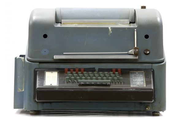
Breaking News!
(Imagine the sound of a chattering teletype…)
Dave N6DE wanted to remind us of the Cass Awards, in which DXpeditions are recognized for working the highest number of unique callsigns during their operation. There’s also a fun article there called “Too Many Awards” that is worth a read.
Contest Results Posted. A flurry of recent preliminary and final contests results have hit our inboxes recently. Including:
- 2025 CQ WW CW – Final results
- 2025 CQ WW RTTY – Final results (and full results article by your Nugget editor)
- February 2026 NA Sprint – Preliminary results
- February NAQP RTTY – Preliminary results
- 2026 CQ WPX RTTY – Raw scores
Sage advice from the March 4th ARRL Contest Update: “Remember to submit your log after the contest, before the log deadline. Here are some steps to log submission success:
- Before the contest, read the rules.
- Contest within the rules, and your chosen category and class.
- Immediately after the contest, or when you’ve finished the contest, submit your log.”
Direct link to the ARRL Contest Update? Maybe. There is a link at the top of each Update to “view in browser”. For those who may not be able to subscribe here is the link I received for the most recent issue. Let me know if it works for you.
Got news? Send it to me for inclusion in the next issues of The Nugget! – ed.
Recently Posted Articles
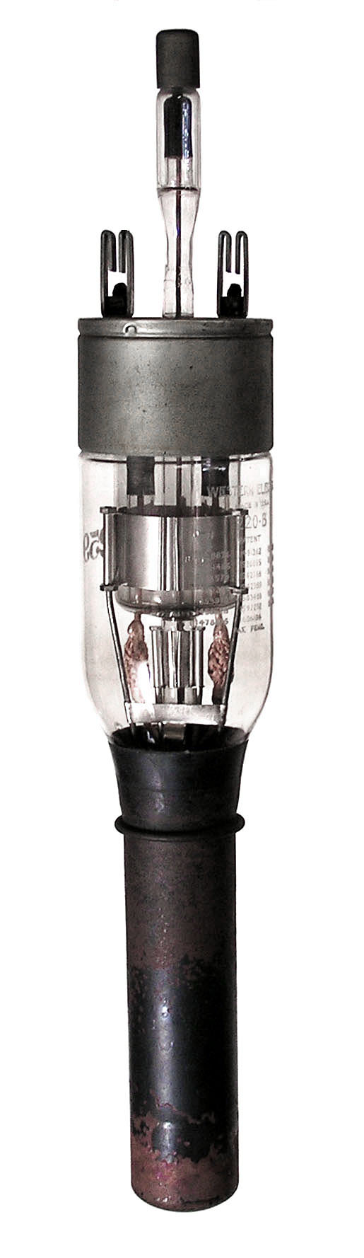
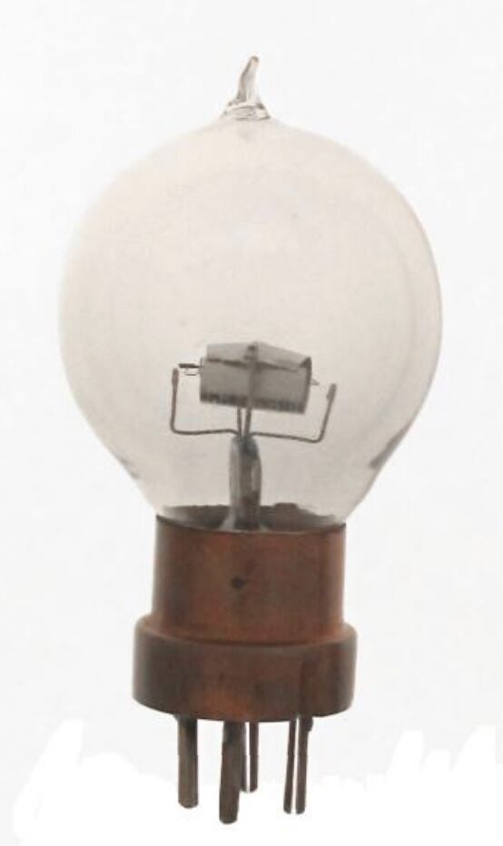
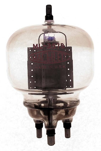
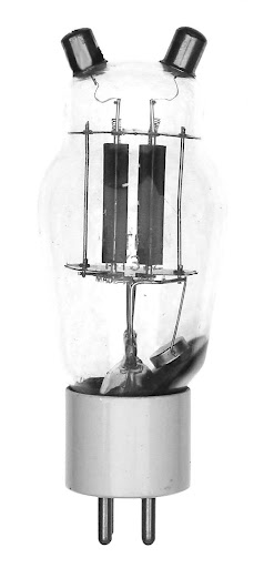
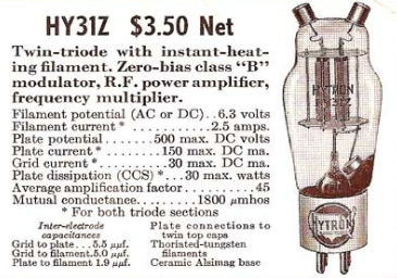
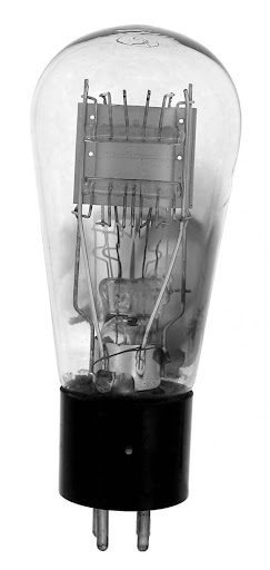
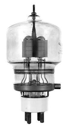
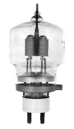
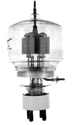
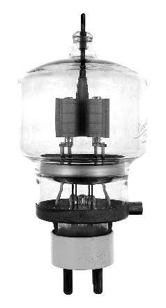
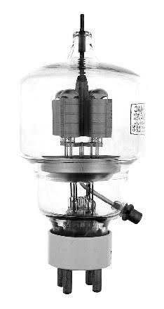
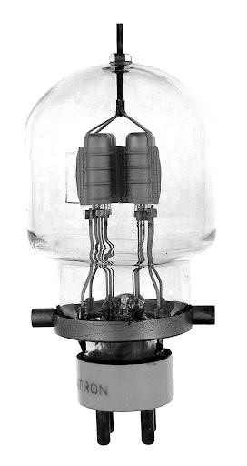
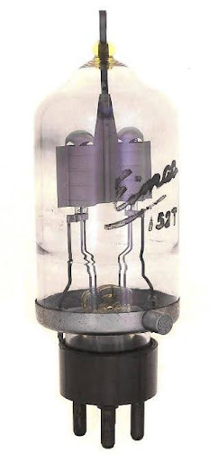
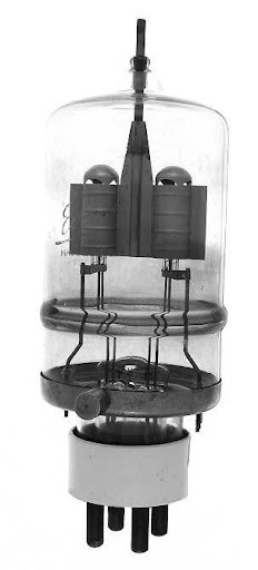
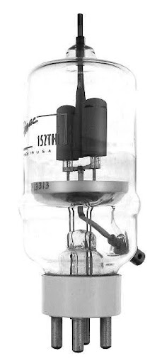
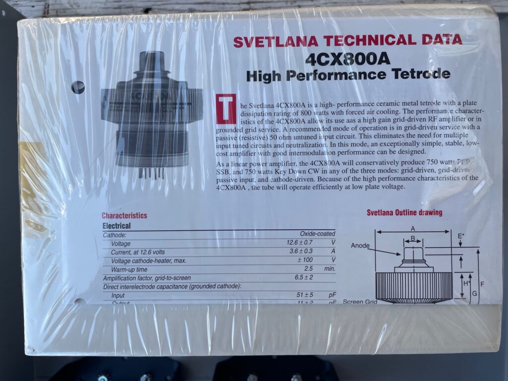
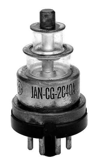
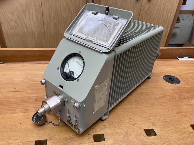
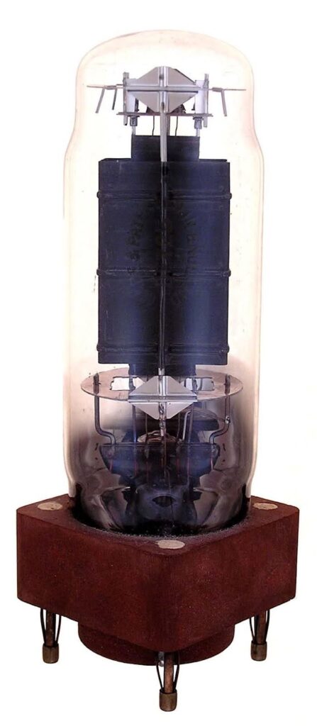
Tube of the Month – March 2026 – Norm N6JV. Some major wattage this month!
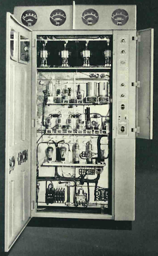
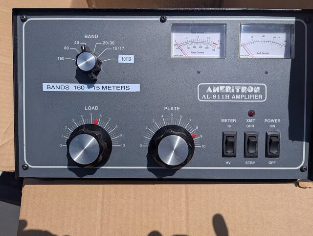
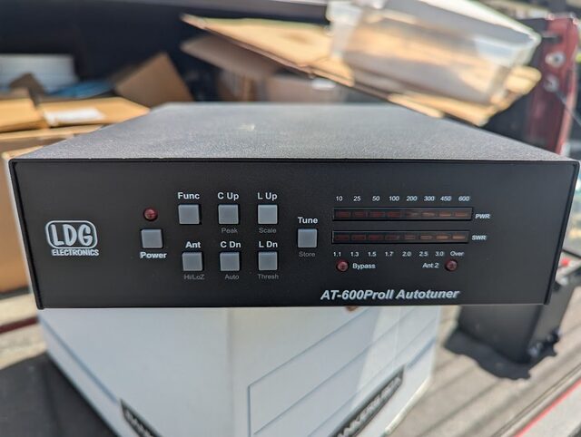
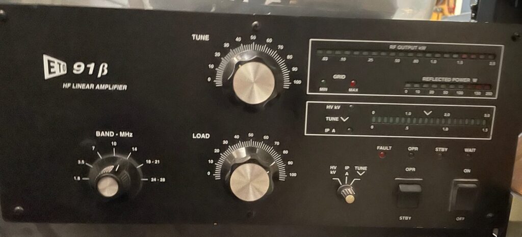
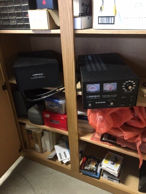
New! Speaking of wattage, A Survey of Solid State Power Amplifiers – Dave N6DE.
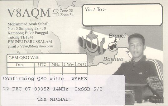
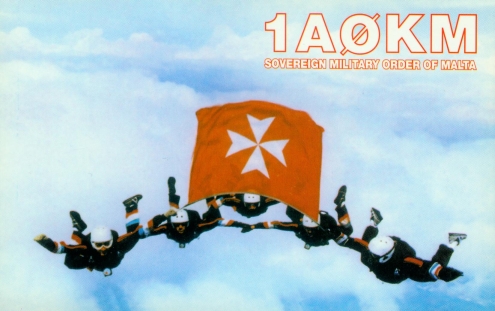
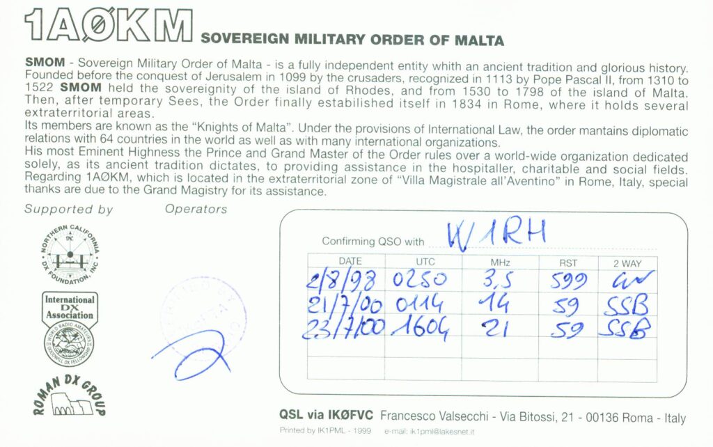
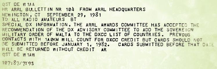
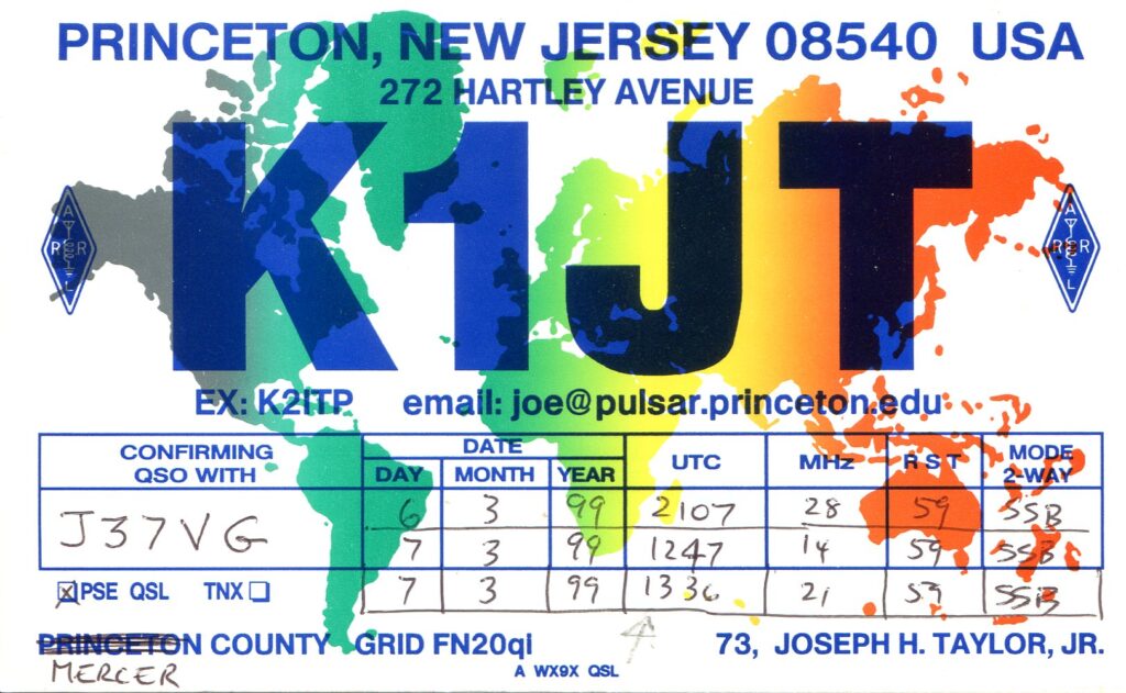
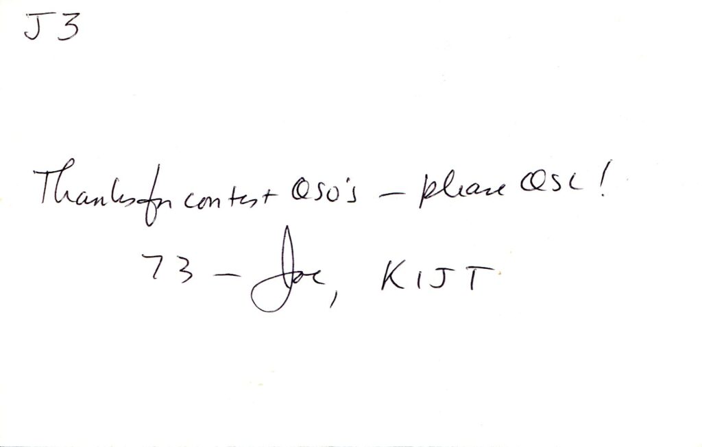
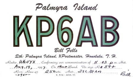
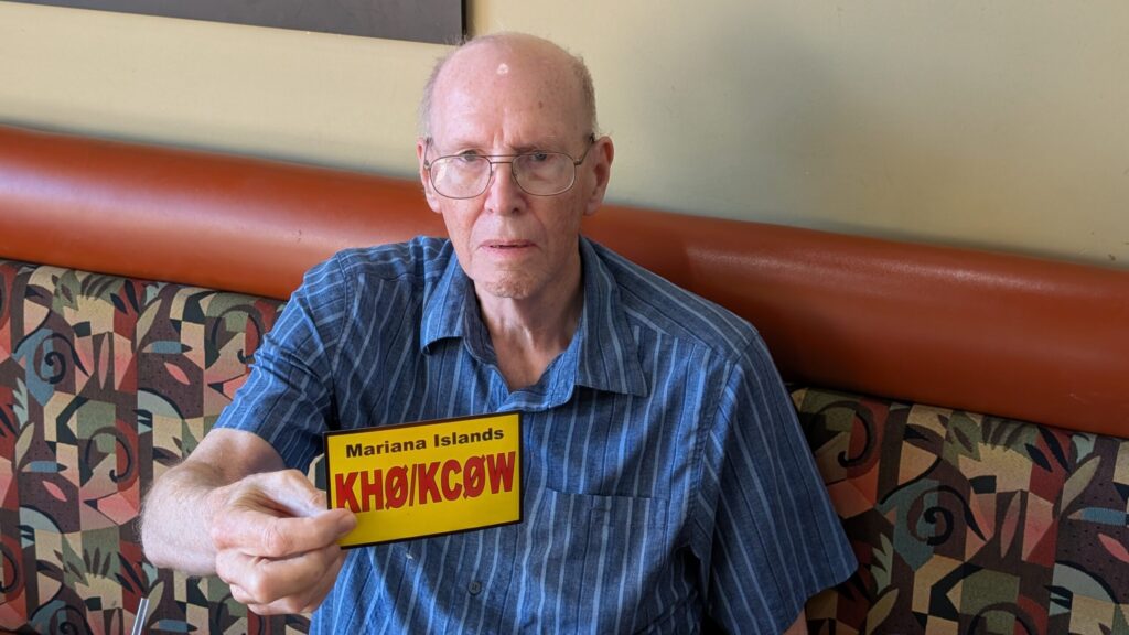
QSL of the Month – March 2026 – Bob W1RH
Videos!
Subscribe to our YouTube channel!
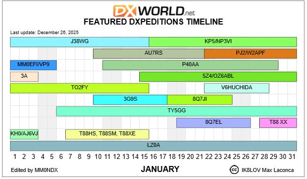
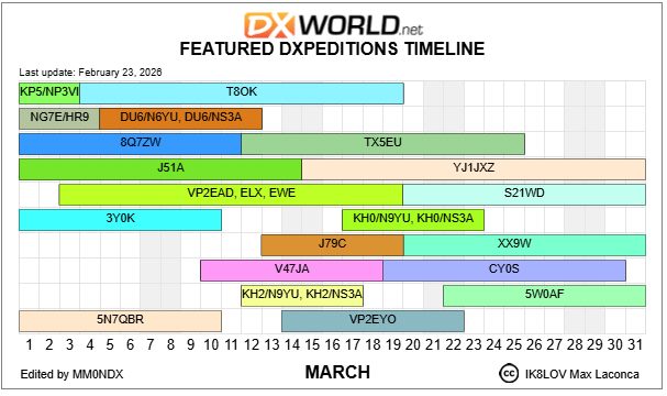
DX…
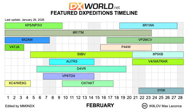
DXpedition Timeline (updated regularly) – Via DX-world.net
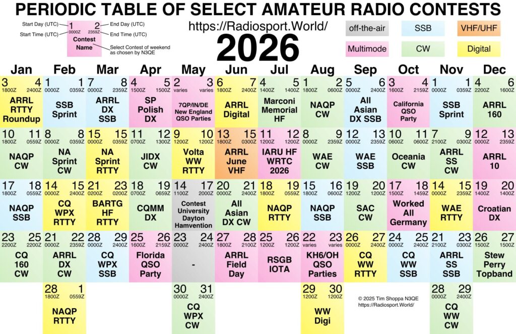
Upcoming Contests
Focus contests for 2026-2027 should be on the agenda in the next couple of meetings – think about which contests you’d like, and contribute to the decision!
Other contests of note coming up in the next month or so, via contestcalendar.com:
- March 21-23: BARTG HF RTTY Contest
- March 28-29: CQ WPX Contest (SSB)
- April 11-12: JIDX CW Contest
- May 30-31: CQ WPX Contest (CW)
State QSO Parties (via statesqoparty.com) – It’s that time of year when the major contest season winds down, but fortunately we have a bumper crop of State QPs for April:
- March 21-22: Virginia QSO Party (CW, Phone, Digital (RTTY etc. no FTx))
- April 4-5: Louisiana QSO Party (CW, Phone, Digital (RTTY etc. no FTx))
- April 4-5: Mississippi QSO Party (CW, SSB, RTTY, FT4/8)
- April 11-12: New Mexico QSO Party (CW, Phone, Digital)
- April 11-12: Missouri QSO Party (CW, Phone, Digital (RTTY etc. no FTx))
- April 11-12: Georgia QSO Party (CW, SSB)
- April 11-12: North Dakota QSO Party (CW, Phone, Digital (RTTY/PSK))
- April 18-19: Michigan QSO Party (CW, SSB)
- April 18-19: Ontario QSO Party (CW, Phone)
- April 19: Quebec QSO Party (CW, Phone)
- April 25-27: Nebraska QSO Party (CW, Phone, Digital (non-FT8), FT4/8)
- April 25-26: Florida QSO Party (CW, Phone)
- Whew!
Classifieds
C’mon folks, buy this stuff! Make offers!
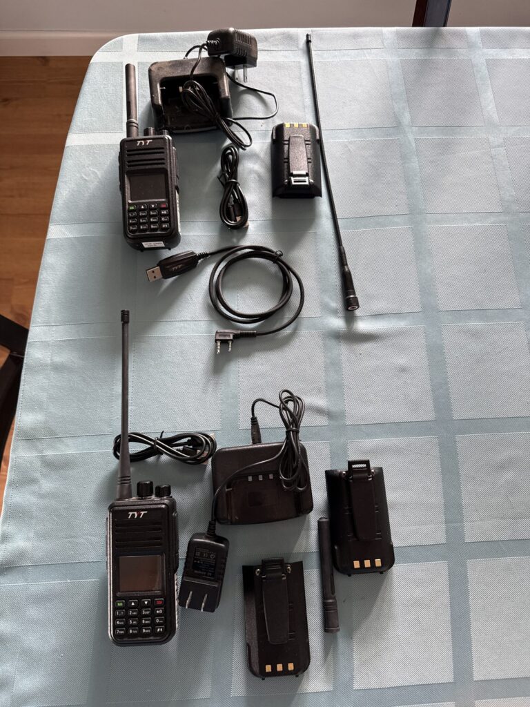
Rick NK7I (Rick.NK7I@gmail.com) notes that “The NCDXC repeater is looking at having DMR access soon so if you’re a member you may want a DMR radio to access it (or via your local DMR repeater or hotspot IF you’re out of the coverage area). Two DMR capable HT for sale here.
- 1 TYT MD-380 UHF HT; DMR and FM/NFM (25/12.5/6.25 KHz width) capable; with charger, spare (NEW 50% more capacity) battery and programming cable; ham, GMRS, FRS and commercial capable. * $100
- 1 TYT MD-380 VHF HT; DMR and FM/NFM (25/12.5/6.25 KHz width) capable; with charger, spare (NEW 50% more capacity) battery and programming cable; ham and commercial capable * $100
* These are nice radios. One really useful feature is being able to load multiple zones into the radio at programming time; so as your needs change, simply change zones (home, cabin, GMRS, vacation location). Programming software is free, available online. Buy both TYT radios, I’ll cover the shipping and add one extra battery (total 5). Useful on DMR or analog repeaters, or a DMR hotspot to talk around the planet. Both HT’s are in excellent condition, rarely used outside and never mobile. Sales to non-ham licensed folks will have the ham programming removed before transfer.
Rick also has “1 Midland commercial 6M radio (FM, 100 watts) with remote head and programming cable (software if wanted). Programmed for all 6M repeater pairs and some simplex, there is a programmable lower power out option too. $100 (plus shipping). This was a EDCARC club purchase some years ago; no 6M FM activity here; it’s just taking up space.”
For Sale and Wanted: Skip N6NFB is selling a US Tower TX-455 (used, very good) with tilt fixture, Yaesu 800 rotor, and 15 foot mast tube $1100. And also selling a US Tower MA-40 tubular tower. New old stock, still on shipping pallets. $250.
Skip is also looking for “a fairly recent HF radio. FTDX 3000 or similar. My trusty old 756proIII developed a problem during the recent contest and took me out of it. Skip – N6NFBskip@gmail.com
Wanted: Rohn-25 tower sections, bottom plate, wall stand off, & top section. If you have any of thiese pieces, let me know along with the price.
Dave, w6de – 530-409-7877 – v8dave@gmail.com
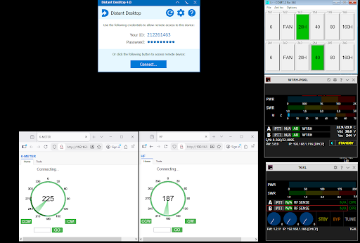
For Sale: Bob W1RH has a WaveNode WN2 Digital Watt Meter, with four HF sensors. This unit sells new for $385, with a single sensor. I have been using is in an SO2R configuration with a sensor on the input and output of each amplifier.
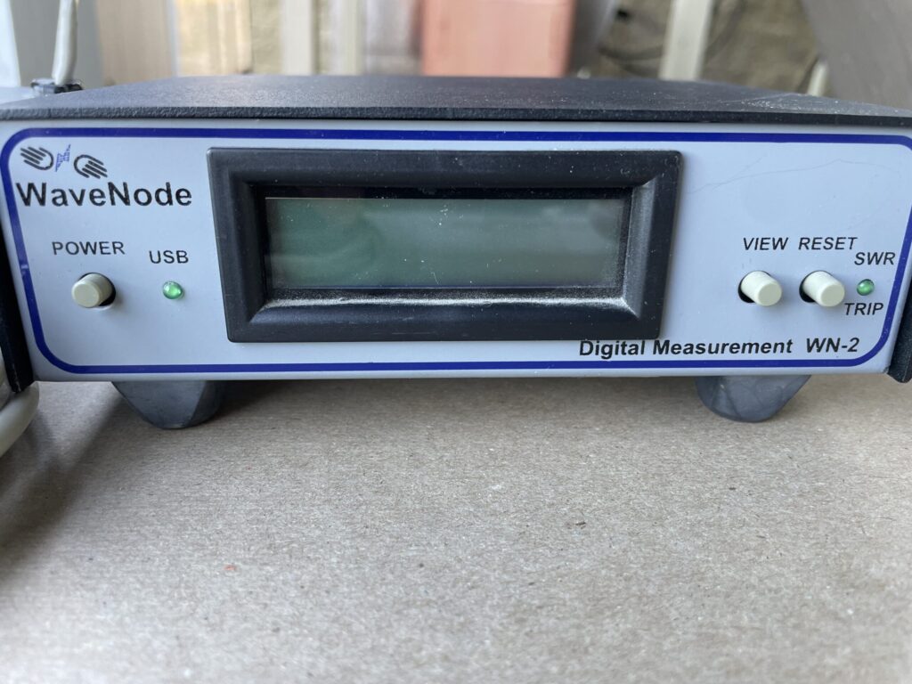
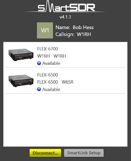
That way, I can always see my input and output power. Rick, W6SR, who uses my station remotely more than I do, has depended on the software display to know how much power he’s running.
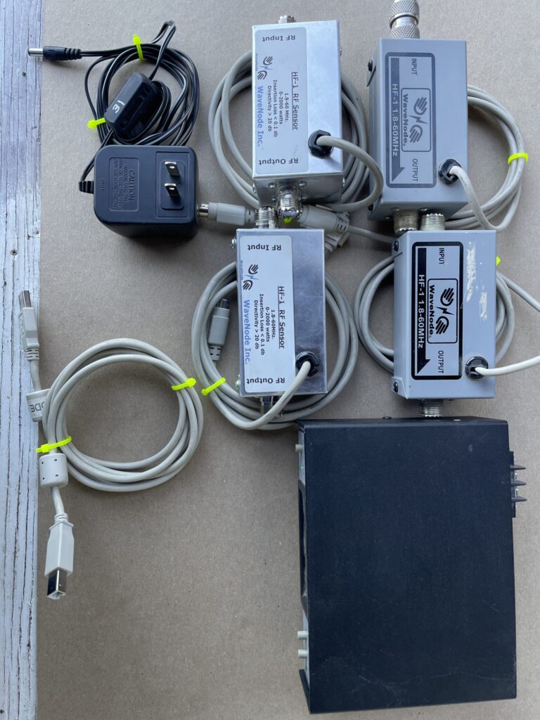
There are several options for the look of the computer display. And there are several other features such as rotator control and antenna switching but I have just used the wattmeter function.
I’m selling this because I have purchased the Flex PGXL amplifier, which has built in and remotable watt meters. It can be yours for $200.
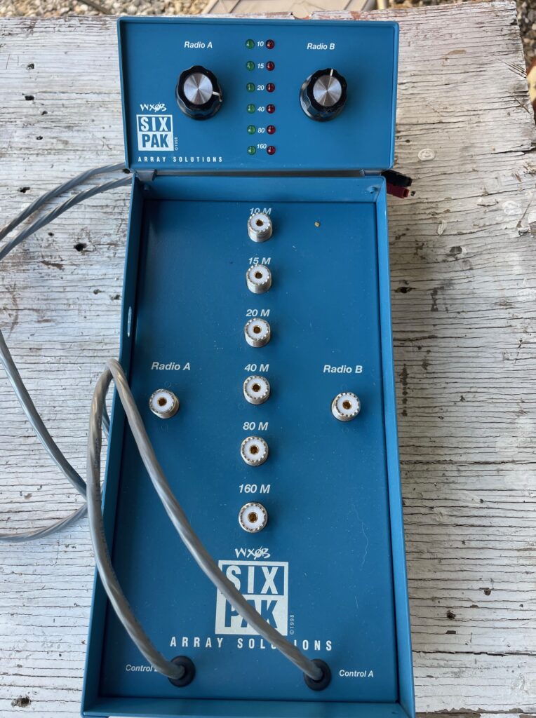
Bob also has for sale an Array Solutions 6-PAK 6 port SO2R antenna switch – $250
Contact Bob W1RH w1rh@yahoo.com.
For Sale: New, never used, EHU for BigIR / $250 or best offer – Thank you, Steve / NC6R nc6r4dx@gmail.com
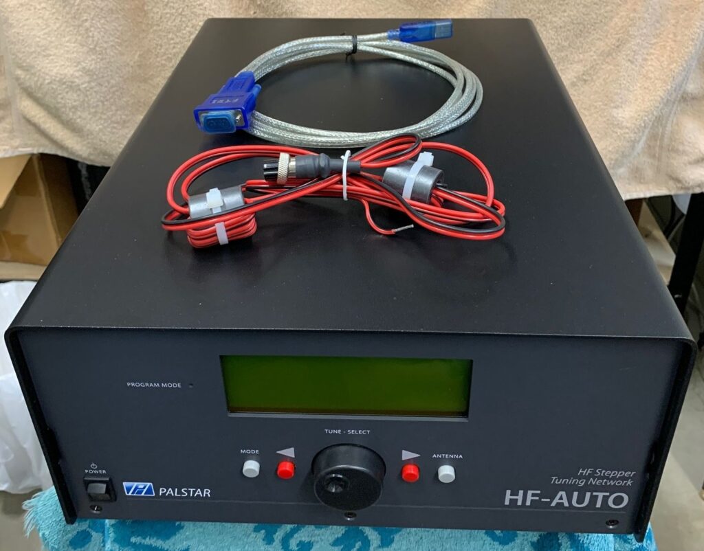
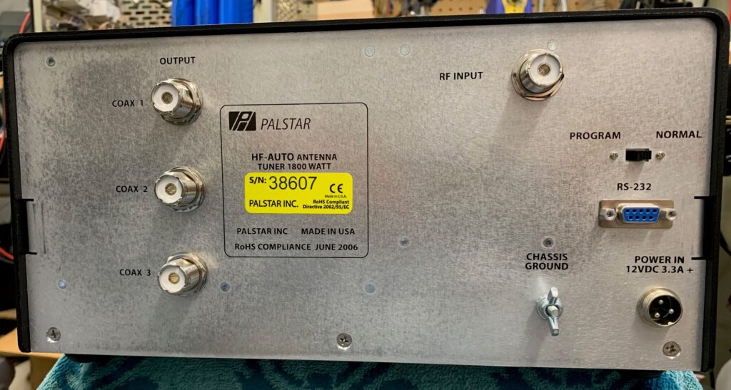
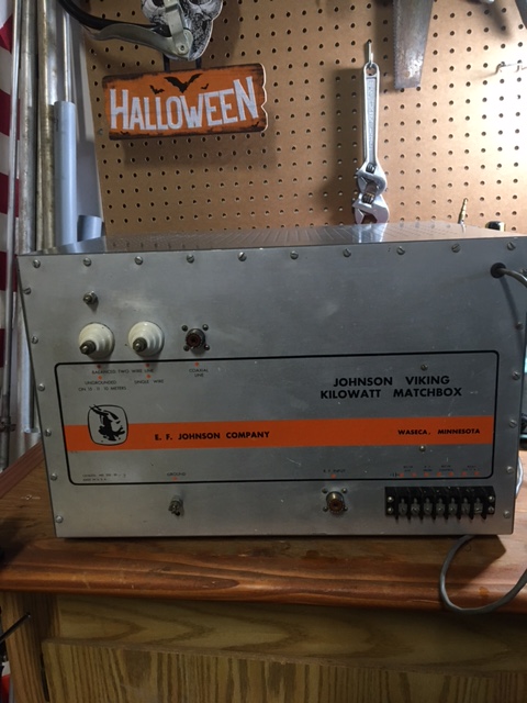
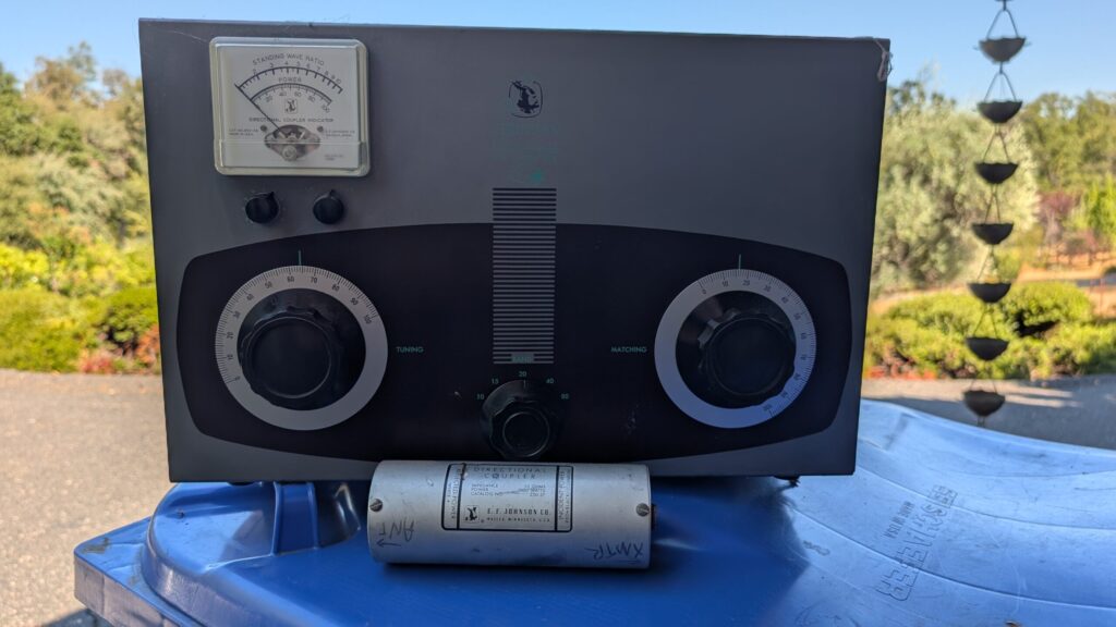
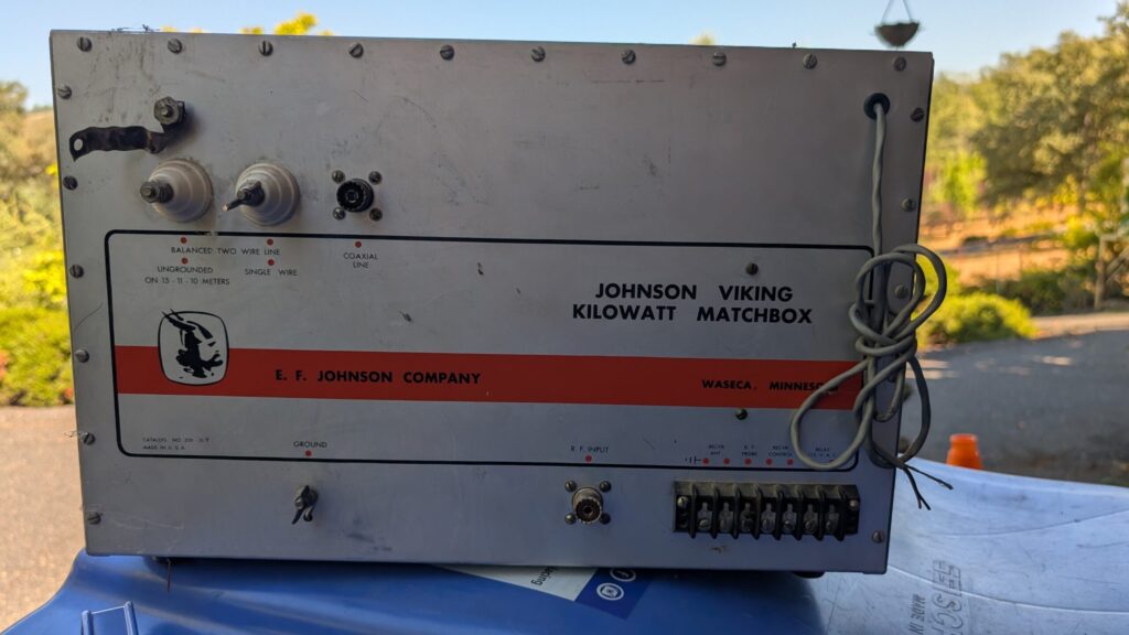
High Power Antenna Tuners: Have you always wanted a Big Johnson? Now’s your chance! I bought this EF Johnson Kilowatt Matchbox years ago at a hamfest and never used it – darn those resonant antennas – so I have no idea of its actual condition. Is said to be able plenty more than 1000 watts, and can tune a balanced antenna as well as something at the other end of a coax. Includes the directional coupler. $150 or best offer. Jeff WK6I wk6i.jeff@gmail.com.
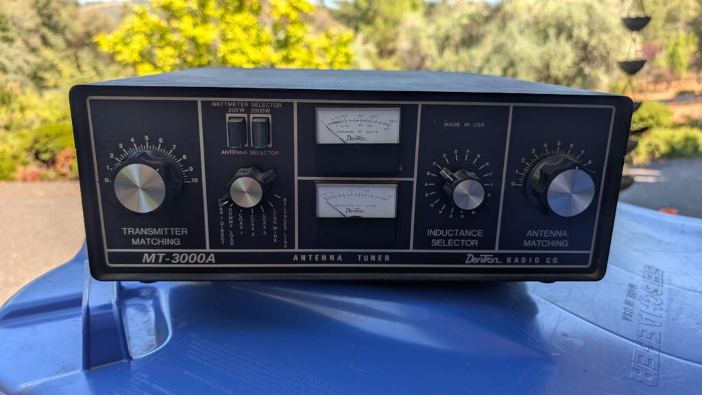
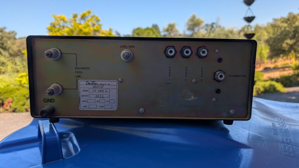
I also have a big Dentron MT3000A. Same story, never used it. This unit includes an antenna switch, dummy load, and can also handle a balanced antenna. $200 or best offer. Jeff WK6I wk6i.jeff@gmail.com.
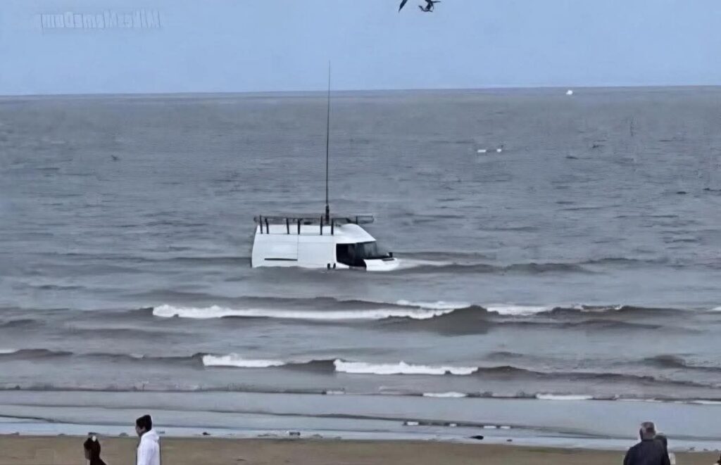
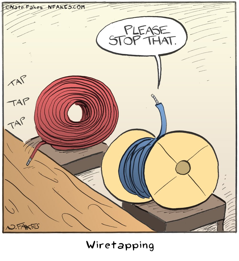
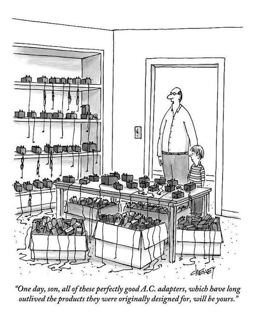
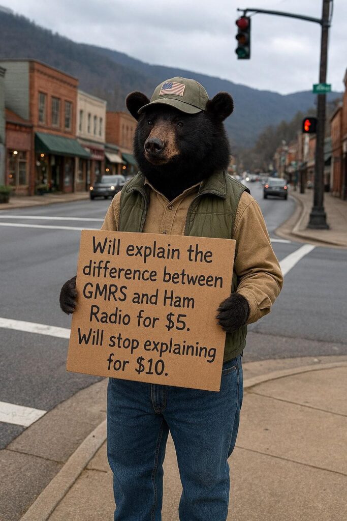
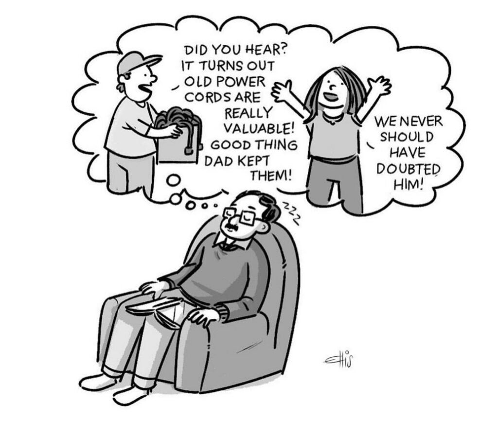
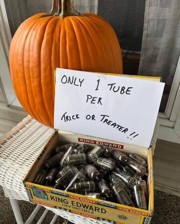
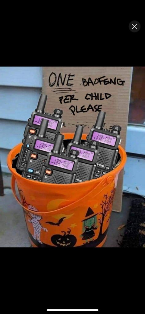
Humor!
A few more things that popped up around the web this month:
Send more funny stuff for the next issue! – Ed.
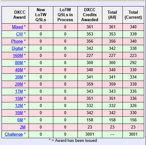
ClubLog DXCC Standings
Standings for 2026 as of 15 March. You can see complete MLDXCC standings on ClubLog here.
Overall
| 1 | NK7I | 143 |
| 2 | K6YK | 142 |
| 3 | W1SRD | 133 |
| 4 | K6RIM | 132 |
| 5 | W6DR | 117 |
CW
| 1 | K6YK | 120 |
| 2 | K6RIM | 107 |
| 3 | W6DR | 93 |
| 4 | K6OK | 80 |
| 5 | NO5Z | 38 |
Phone
| 1 | W6RKC | 48 |
| 2 | NC6R | 47 |
| 3 | K6TQ | 41 |
| 3 | WU7W | 41 |
| 4 | K6YK | 37 |
| 5 | K6LR | 24 |
Data
| 1 | NK7I | 143 |
| 2 | W1SRD | 133 |
| 3 | W6KAP | 114 |
| 4 | K6RIM | 98 |
| 5 | K7QDX | 94 |
10 and 20 Years Ago in The Nugget
The March meeting was held at a Denny’s in Cameron Park. When was the last time we met at a Denny’s? John K6MM gave a talk on the K5P DXpedition.
VP Dennis NJ6G told a tale of woe, in which he had taken the Friday off work for the ARRL DX SSB Contest to properly prepare, only to be waylaid by an avalanche of software updates, hardware failures, and honey-dos. “So before the next contest in a few weeks I need to go through the power distribution system, find out why my vertical isn‟t tuning, and make sure I have the latest and greatest logger version. Shouldn’t be a problem, I have that Friday off.”
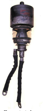
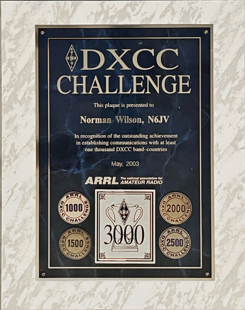
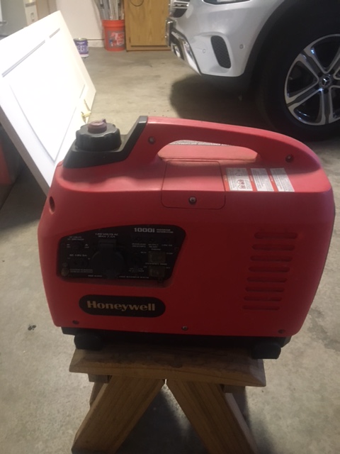
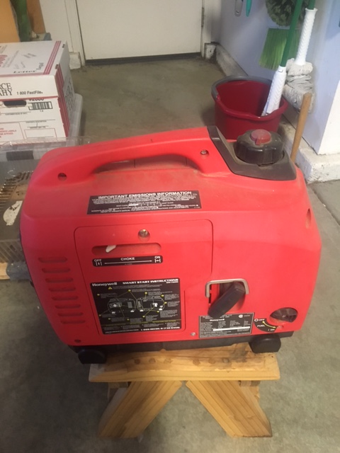
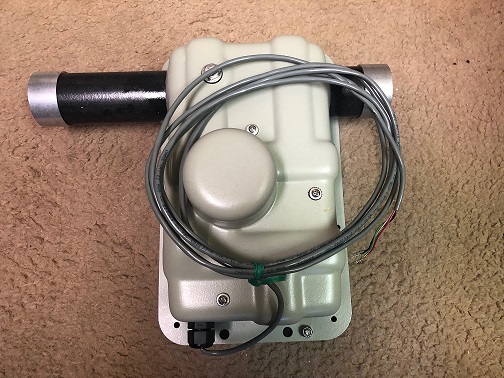
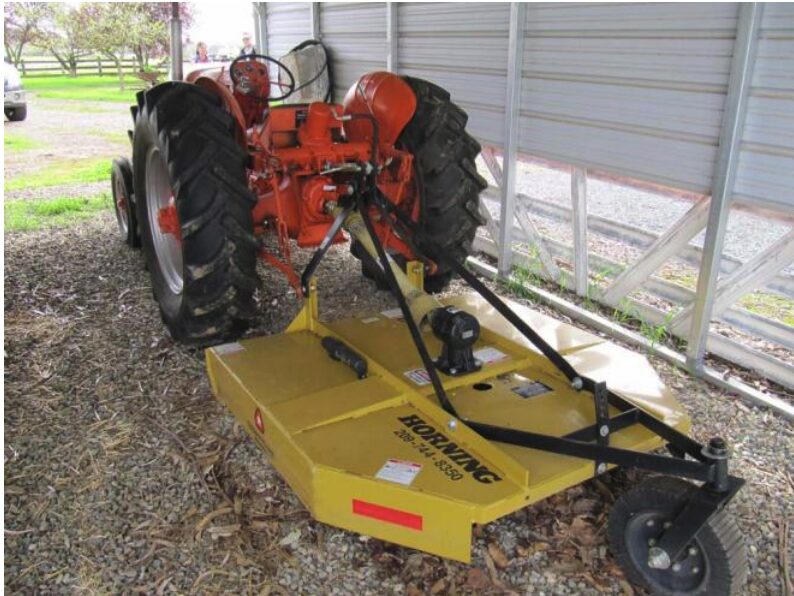
Norm N6JV not only gave us “TUBE WARS – EPISODE 2 The Kaiser Awakens” (you’ll want to go read that), but he also had an interesting item for sale. “Original owner: N6JV. Small tract house in South Sacramento. Many special features that include drive-by shootings, drag racing in the street and several neighbors growing pot in the garages with illegal grow lamps
and ballasts.” The good news is that the “New house is twice the living area and with 5 acres, it has open fields for the cultivation of aluminum and steel structures.” Pictured below, Norm’s new weed eater.
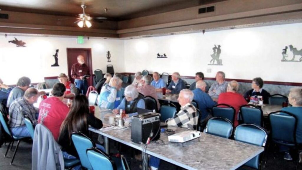
President Rich NU6T made a plea “At our February meeting, we recognized that some general clubs may appreciate having an experienced DXer or Contester make a brief presentation to introduce prospective new folks to our favorite aspect of Amateur Radio, and perhaps bring a few new members to MLDXCC. Some may look forward to public speaking like an old CW man looks forward to a phone contest, but we could use a list of potential speakers who would be willing, on occasion, to visit a local club and represent our club and interests.”
Whatever happened to Field Day? “Members indicated interest in working Field Day and the ARRL DX, WPX and CQP contests as a Club, and perhaps working toward competitions within the Club to rally the troops. George Staudacher, KI6CG, suggested that along with posting the scores, members should e-mail the summary sheet to Rick Karlquist, N6RK, as Contest Chairman… Jim Venneman, WX6V, is Field Day Chairman and Rick, N6RK will do what he can in preparation for CQP.”
Did these snippets from years ago trigger any good memories? If so, please send them for inclusion in the next issue of The Nugget!
Resources
Check out the Resources menu up there at the top of every web page for useful DX and contest info.
Prepared for the MLDXCC by Editor and Webwookie Jeff WK6I. Please do send me any corrections, omissions, or material for future issues of The Nugget. It is much appreciated!