Also two MLDXCC members placed first for call area 6 in their respective categories: Mike K7QDX in the Limited category, and Richard NC6RJ in the Formula 100W category.
by Norm Wilson N6JV – Visit the museum at N6JV.com
R3 – RECTOBULB
In the July, 1927 issue of QST magazine, an advertisement was published featuring the “6EX Rectifier” by a company named the National Radio Tube Company of San Francisco, CA. The call 6EX was held by a Garrett Lewis. Rectifiers like the 280 and the 281 had become available by 1927 for receivers and low power transmitters, but no rectifiers that would handle the voltage and current required to power the larger transmitting tubes hams were wishing to use. Arc rectifiers could be used but, they weren’t practical for most hams. It was unusual to see a tube named alter a ham. Hams would be assigned prefixes sometime in 1928.
The 6EX was later designated the R-3 and started life as a high vacuum type, but the final product was mercury vapor with an indirectly heated cathode. The maximum plate voltage was 7500 peak inverse volts at 250 ma. The filament ran on 10 volts at 1.7 amps. The tube had a standard UX base and a threaded stud out the top for the plate connection.
I don’t know how well the tubes were selling, but Lewis had a ham friend in Southern California who wanted to replace the ARC rectifier he had sold him and build a new power supply. The friend was Don Wallace, 6AM, and he wanted to go big. Lewis had also sold Wallace a re-built F328A which was a water cooled, 5 KW triode.
Don didn’t like QRP. Don bought six 3 KVA pole pigs that were 220 volts in and 6000 volts out from the power company and mounted them in a rack with six of the new R-3 rectifiers. The new power supply would be wired for six phase operation. The schematic and rack photo are copied from QST magazine of February, 1928, where Don and Robert Kruse of the QST staff, wrote a 9-page description of the final power supply. Six phase rectification results in an output ripple of six times the input ripple frequency. In 1928, 360 Hz was considered a good CW note and adding a filter condenser would be very expensive. The R-3 may have never been a commonly used tube as in a few years, the RCA 866 went into production and the R-3 became only a collectable. Before WWII, Lewis moved to Silicon Valley where Lewis Electronics was formed and participated in tube production for the war effort. In 1949 Lewis and Kaufman was organized and operated into 1956. In about 1962, I bought two 3 KVA pole pigs from PG&E for $3 per KVA.
Round Table Pizza, Jackson Meeting was called to order at 12:19 p.m. by Treasurer Sue Allred, K6SZQ. There were 12 attending in person, with 2 more attending via zoom. Of these there was one guest. Sue welcomed everyone. Each member and guest introduced themselves.
Old Business:
The January minutes were published in the February Newsletter. Rick Casey, W6RKC, moved to accept the report as published. Dave Sanders, K6TQ, seconded the motion, which passed unanimously.
The November and December treasurer’s reports were published in the February newsletter. Rich Hill, NU6T, moved to accept the reports as published. Stefan Nicov, AF6SA, seconded the motion, which passed unanimously.
New Business: None.
Member Achievements:
Rick Samoian, W6SR, worked VK9DX Norfolk Island on 6 meters.
Jeff Stai, WK6I, got the banquet organized for the Visalia International DX Convention
Announcements/Discussion:
The upcoming International DX Convention was discussed, along with the uncertainty with future events.
Bob Hess, W1RH, while managing the livestream, showed photos of Stefan Nicov’s Solid State HF amplifiers and discussed the possibility of him doing a presentation on them.
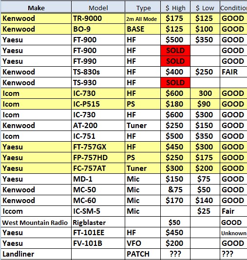
Bob Hess also passed around a list of equipment for sale from Tony Dowler, K6BV.
Next Meeting: Proposed date to be May 10, the location is Habanero Hots in Lodi.
Adjournment: Rick Samoian, W6SR, moved to adjourn the business meeting and move to the presentation. Jeff Stai, WK6I seconded the motion, which passed unanimously. Meeting was adjourned at 12:50 p.m.
Presentation: John Stanley, K4ERO, gave a fascinating presentation on Antipodal Focusing and its effect on ionospheric propagation near the opposite side of the earth from the transmitter. You can also get further information from his article in the March, 2025 QST.
Respectfully Submitted, G. “Skip” Chraft, N6NFB
Treasurer’s Report
Sue K6SZQ reported that, given the low level of activity, she’s going to switch to quarterly reporting. Look for the first quarter report in the next issue of The Nugget.
President’s Corner
Hi MLDXCC’ers,
Well, here I am as President of this club again. I swore it would never happen but Steve, NC6R, termed out. In an attempt to keep the club healthy, I made the suggestion that I’d take over as President and Steve will be VP… with one condition… Steve will keep running the meetings and I’ll continue to arrange the meetings and speakers. So, nothing has really changed other than a “loophole” in the Bylaws that allows us to continue as we have over the past three years.
I want to thank John Stanley, K4ERO, for a terrific presentation at last month’s meeting on the subject of Antipodal Focusing, meaning propagation from your QTH to the opposite side of the earth. We did record the meeting and, hopefully, Jeff will find a way to post the link on the all-new MLDXCC website.
I can’t thank Norm, N6JV, enough for what he has done for our website and newsletter. Without Norm’s constant “nagging” for content, we would not have had a newsletter and website with the great content we have had over the years. Alas, Norm has finally found someone to take over the website and Nugget. We all thank Jeff, WK6I, for taking on the challenge of filling Norm’s big shoes. Keep doing those great tube articles, Norm!
We have some really good speakers lined up for the upcoming months. Our May speaker will be Chuck, NA6XX, who will give a presentation on 6-meter DX’ing and propagation. Chuck, who lives in San Jose, will be driving to Habanero Hots, in Lodi, to give us his presentation in person. I also plan to stream this meeting. The date is May 10th.
A few others have agreed to do upcoming presentations. Stu, K6TU, will give a talk on his K6TU.net HF propagation site Craig, K9CT, will give us a presentation on his super contest station. Gary, NA6O, has also offered to give another one of his very entertaining talks. Other presentation for future months are in the works.
Both Steve and I have resisted streaming our meetings in the past for various reasons. We will be streaming more of our upcoming meetings. I do hope we can get more of our members from outside the core area to attend. Maybe even Will, from down south who often participates in our reflector conversation, will show us what he looks like!
In our February meeting, I did a contesting and DX’ing quiz, which seemed to get rave reviews, so we may do another one of those in the upcoming months. The February quiz, and the answers, are in this month’s nugget.
Last, and certainly not least, several of our members participated in the CQ WPX SSB contest last weekend at WC6H’s contest station. Besides Rich, the operators included Jeff (WK6I), Steve (NC6R), Gary (VA7RR), Tim (NU6S), and Barry (K6ST). The team did a whopping 14,097,405 claimed score to support NCCC’s effort.
For those headed to Visalia, travel safe and have a great time! – Bob W1RH
Tony K6BV has the following items for sale, please contact him at dxer@k6bv.net.
ClubLog DXCC Standings
As of 31 March 2025. You can see complete MLDXCC standings on ClubLog here.
Overall
1
NK7I
211
2
W1SRD
200
3
W6DE
181
4
K6YK
164
5
K6OK
154
CW
1
K6YK
136
2
NO5Z
113
3
N6WM
103
4
NA6O
102
5
W1SRD
95
Phone
1
W1SRD
112
2
N6WM
111
3
NO5Z
106
4
K6YK
101
5
K6TQ
81
Data
1
NK7I
200
2
W1SRD
168
3
W6DE
161
4
K7QDX
149
5
K6OK
128
Resources
Check out the Resources menu up there at the top of every web page for useful DX and contest info.
Prepared for the MLDXCC by Editor and Webmaster Jeff WK6I. Please do send me any corrections, omissions, or material for future issues of The Nugget. It is much appreciated!
At the February MLDXCC meeting Bob W1RH conducted a sort of trivia contest of various DXing and contesting questions. Here are the questions with the possible answers to choose from.
1 – The Following Contests Allow Self Spotting. Check all that apply:
ARRL SWEEPSTAKES CQWW IARU WORLD CHAMPIONSHIP NAQP
2 – K1LZ HAS A M/M REMOTE CONTEST STATION IN WHICH STATE?
Vermont Maine New Hampshire Rhode Island Massachusetts
3- In the North American QSO Party, the exchange is state/province and name. You do not need to use your own name. In the January NAQP, WO4O used W1N as a special event callsign. What name did he use?
Chiefs Bills Trump Eagles
4 – THE P49Y CONTEST STATION IS LOCATED IN WHICH ENTITY?
Aruba Bonaire Curacao Carriacou
5 – THE WINNERS OF THE 2024 SS CLUB COMPETITION ARE (Unlimited, Medium, Small):
At the February MLDXCC meeting Bob W1RH conducted a sort of trivia contest of various DXing and contesting questions. Here are the questions with the correct answers.
1 – The Following Contests Allow Self Spotting. Check all that apply
ARRL SWEEPSTAKES NAQP
SELF SPOTTING MEANS THAT YOU SPOT YOURSELF INSTEAD OF RELYING ON OTHERS
2 – K1LZ HAS A M/M REMOTE CONTEST STATION IN WHICH STATE?
Maine – Krazzy is from Bulgaria (LZ prefix).
3 – IN THE LAST NAQP, WO4O USED THE SPECIAL EVENT CALL, W1N. WHAT NAME DID HE USE?
TRUMP
4 – THE P49Y CONTEST STATION IS LOCATED IN WHICH ENTITY?
Aruba – Also P49L. Built by Carl, AI6V, as P49V. P49Y is Andy, AE6Y. P49L is John, W6LD
5 – THE WINNERS OF THE 2024 SS CLUB COMPETITION ARE (Unlimited, Medium, Small):
PVRC, MLDXCC, PL259 – (we hope)
6 – THE MLDXCC CLUB CALL IS
K6AO – Was John Fogg, Portola Valley, CA
7 – A FT8 CONTEST QSO CAN BE LOGGED WHEN YOU RECEIVE:
ALL OF THE ABOVE
8 – A STATION OPERATING 2BSIQ CAN USE WHICH MODES?
ALL OF THE ABOVE – TWO BAND SYNCHRONIZED INTERLEAVED QSO’S.
9 – 4U1WB COUNTS FOR WHICH DXCC ENTITY?
USA (WORLD BANK)
10 – HOW MANY CURRENT DXCC ENTITIES ARE THERE?
340
11 – THE PREFIX, FP, IS IN WHICH CQ ZONE?
5 – ST PIERRE AND MIQUELON
12 – THE VP8PJ DXPEDITION OPERATED FROM:
SOUTH ORKNEY ISLANDS
13 – THE PREFIX, VP9, IS IN WHICH CQ ZONE?
5
14 – WHAT WAS THE CALL OF THE FAILED BOUVET DXPEDITION?
3Y0Z – THE DXPEDITION FAILED BECAUSE THEY COULD NOT SAFELY LAND. THE BOAT GOT TO APPROXIMATELY ONE MILE FROM THE ISLAND
15 – ON A MULTI-ELEMENT YAGI, THE AZIMUTH AT WHICH MAX SIGNAL REJECTION OCCURS IS:
TO THE SIDE – A SHARP BROADSIDE NULL ABOVE THE ANTENNA
16 – THE BATTLE CREEK SPECIAL IS A:
MULTI-BAND VERTICAL (40/80/160) – WERE OFTEN USED ON DXPEDITIONS
17 – JAMES BROOKS HAS RECORDED MANY DXPEDITIONS. WHAT IS HIS CALL SIGN?
9V1YC – HE HAS FILMED MANY MAJOR DXPEDITIONS. HE OWNS A PRODUCTION COMPANY IN SINGAPORE
18 – THE VK0IR DXPEDITION WAS ON WHICH ISLAND?
HEARD ISLAND – 1997
19 – THE K5K DXPEDITION 2000 TO KINGMAN REEF COUNTS FOR DXCC
NO (Deleted March 19th, 2016 – was administered by US NAVY. Changed to US Fish and Wildlife, which also administers nearby Palmyra. Now counts as Palmyra/Jarvis.
20 – WHO COINED THE PHRASE, THE DESERVING?
HUGH CASSIDY, WA6AUD (first used in the West Coast DX Bulletin)
I’ve seen the final results for the 2025 RTTY Roundup and here are the results for the MLDXCC. The club competed in the Medium Club category and came in 9th place.
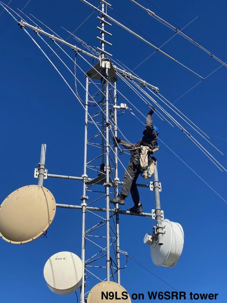
Everyone knows how to rotate their Yagi antenna: Just turn the knob and away it goes. But this article isn’t about that rotation, it’s about rotating it a different way, for maintenance. When your beam has a problem wayy out where you can’t reach it, the usual expectation is that the whole thing is going to have to come down off the tower. Many of us have seen balun failures or lost the tip off of an element or had an element twist on the boom, and there’s no obvious or easy way to reach it. It’s bad enough that we have to hire a climber, and even worse when the work involves tramming the whole shebang down to the ground and back up. Thankfully, professional tower busters have tricks that save us much time and effort. The first time you see it, the light goes on and it’s obvious… If only you had thought of if first!
The simplest trick is to rotate the Yagi by loosening the boom in the boom-to-mast clamp, allowing the boom itself to rotate. This lets the elements swing down alongside the tower. Now it’s possible to climb up or down and reach at least the elements that are close to the tower. Our local climber Mark, N9LS, did a service call at my station W6SRR where some plastic clips out on the elements had slipped out of position. He was able to reach them and fix the issue easily.
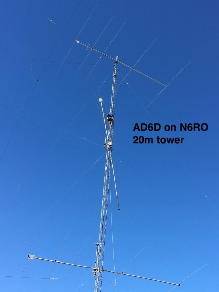
The more elaborate and flexible trick is to dismount the Yagi entirely while temporarily supporting it at its balance point with some combination of slings, ropes, and a come-along. At N6RO, we had a balun failure on a long 20m Yagi and Hector, AD6D, used this method. Once the antenna is free-floating, it’s easy to position it at any angle along the tower, allowing access to anything that needs attention.
So be sure to consult the pros when you have a problem up the tower. They may even show you a different way to rotate.
by Norm Wilson N6JV – Visit the museum at N6JV.com
WD-24
Westinghouse was one of the first American companies to commercially produce vacuum tubes. RCA held the triode patent so Westinghouse and General Electric made tubes for distribution by RCA. These companies also developed experimental tubes for their own use and to develop new products and perfect construction techniques. The featured transmitting triode was found at a swap meet. I don’t think I paid much as nobody knew what it was other than an early, primitive triode that was probably made about 1920. Eventually I identified it as a Westinghouse WD-24, but I have no reference source to prove it. All tube collectors have a library of reference material and I think someone knew what it was and supplied the operating voltages and currents. The plate could be run as high as 2000 volts at 250 ma. The filament was 10 volts at 15 amps. The tube stands 12 inches tall. Westinghouse tubes had several prefix codes and often WD was used to indicate a developmental tube.
This tube was made by spot welding rods to support the plate and grid. The ends were connected to internal metal clamps. In operation, the tube was mounted with straps. This system is similar to what de Forest tubes of this period used. The feature that doesn’t make any sense is the square box shaped plate. Making the spacing between the grid and plate uniform, minimizes the creation of hot spots The variable grid to plate spacing may result in an odd-looking set of performance curves. This design didn’t catch on but it is an interesting example of early experimentation.