I have been tracking the performance of Solid-State Power Amplifiers—SSPA for a number of years after having to repair my PW1 multiple times due to my own operator errors. Having a fully automated station is not failure proof in the real world. Most SSPA failures are due to transmission initiated into a load with a SWR of greater that 1.5:1 and almost always fail into a SWR higher than 2:1. More modern designed SSPAs now have better SWR protection than early generation SSPAs. But there are still some SSPAs that are suspectable to damage from operator errors. Best advice is to ask multiple operators about their experience with their SSPA.
What types of operator errors?
Operations such as using a mechanically adjusted antenna tuner [Start transmitting before a pre-stored match adjustment has completed.]. Operating in high SWR area of a non-tune-able frequency area of an antenna. Attempting an antenna tuner match at QRO power levels. Transmitting into the wrong antenna. Not testing into a Dummy Load. SSPA built-in antenna tuners that are not instant-ons changing to the new SWR match.
And the two biggest errors: 1) failure to kill Split on the transceiver when changing bands [VFO A moves to the radio and amplifier to the new band while VFO B stays on the previous band, so you transmit into the wrong antenna; 2) configuration errors in the software apps dealing with station automation.
by Bob Hess, W1RH with help from Rick Samoian, W6SR
Since it’s the end of the year, and since Jeff is always asking for Nugget articles, I thought I’d bring all of you up to date on what Rick, W6SR, and I have been doing with remote operation from my station.
A couple of years ago, Rick asked me about remoting into my station. Rick had been using Fred’s (KH7Y) station, but Fred was in the process of moving to New Mexico.
At that time, my station was set up for SO2R, using a Flex 6700, an Alpha 91B amp and an Ameritron ALS-1300 amp. Antennas consisted of a Force12 C19XR on Tower 1 and two Cushcraft A3S’s on Tower 2. I also had an 80 meter sloper, a 160 meter dipole and a 40 meter rotatable dipole on Tower 1. A loop, placed way down the hill, has been used for receiving.
My location sits on 10.5 acres, 100 feet below the top of a north-south ridge, on the east side. The top of the mountain is 1,800 feet and my lot is 1700 feet at the top and about 700 feet at the bottom…..a very steep fall-off from about 0 degrees to 200 degrees. Much of the Pacific is blocked by the top of the ridge. I can work Europe and Africa, however, when conditions are such that many others cannot. Same goes for the Caribbean and South America.
Rick, who had moved into a community with antenna restrictions, had a Flex Maestro, a Flex 6500 and various items leftover from his previous QTH.
With Flex equipment, it’s very easy to remotely control the radio, but that’s it. When Rick first started using my station, I would have to manually change frequency on the amps and change antennas on the Array Solutions SO2R switch.
A lot has changed since then.
One of the first changes was an EA4TX Remote Box that Rick purchased. This allowed the Array Solutions SO2R switch to be remotely controlled and has been very reliable over the past two years.
Later, I was able to remote the ALS-1300 but it had no 6 meter capability. Instead, Rick purchased an ALS-1306 and later an Acom 1200S. At one time or another, I used all three of these amps for the second side of the SO2R switch but the 91B remained in place as my primary amp.
The next step was to install a 5 element KLM 6 meter Yagi that Rick had in storage. We decided to put up a single section of Rohn 25 and put the antenna at about 10 feet above ground on the edge of a very steep drop-off. It has performed well.
Over this period, I was playing around with various remote desktop programs and settled on a program called Distant Desktop. It’s free and very reliable and Rick uses this program to control just about everything at the station. I added two of Stefan AF6SA’s remote antenna controllers, which appear on the desktop. Also, we used an app for the Acom but there was no app available for the Ameritron amps.
Things really changed for the better as I was wondering the flea market at the Dayton Hamvention this past May. I found a contester selling his 4O3A/Flex Power Genius Amp, Tuner Genius 2 KW tuner, and his Antenna Genius 8×2 antenna switch. We did a PayPal fund transfer and all three items belonged to me. All I had to do was to get them back to California. I should note that the Dayton Hamvention is incredibly organized and has folks standing by with golf carts to carry goods from the flea market out to the buyer’s cars. Wonderful! Once I had it in the rental car, I found a UPS store and $250 later all three boxes were on their way to California.
What is wonderful about adding the 4O3A/Flex devices to the station is that Flex devices talk to each other via Ethernet. This means that serial cables, USB cables, PTT cables etc. are not needed. To tie them all together, I just used the Ethernet connector and coax connectors on each device. Currently, I have yet to install the Antenna Genius switch but we have been using the amplifier and the tuner and they have been incredibly reliable. The amp will easily do 2 KW if you don’t watch your power. Both the tuner and amplifier are configured for SO2R, so no other boxes are required for a SO2R operation other than the 6700 radio, amp and tuner.
Another benefit of using all Flex equipment is that both the Maestro and SmartSDR (Flex software) now have amplifier windows built into the display. This way, when you’re looking at the screen, with the waterfall, frequency and all radio controls, you’re also seeing amp input power, output power, and temperature.
All of this now gives Rick and I a full power remotely controlled SO2R station. There has been no hurry to install the Antenna Genius switch since the EA4TX controller with the Array Solutions antenna switch works so well, but I will get around to replacing the Array Solutions switch with the Antenna Genius switch this spring.
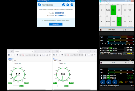
This is what Rick sees on the Distant Desktop display at his house:
Distant Desktop running on a dedicated Lenovo ThinkCentre M93p Tiny desktop computer
While the remote desktop idea is working fine, it’s nowhere near as cool as using Node Red to control everything. I’m working on that and we will be moving station control over to Node Red in the upcoming year.
One problem for us has been dealing with the contest log when Rick and I do a multi-op. I’ll put N1MM up on the remote desktop computer and we both use that and, while it works, there are other issues involving the Flex’s DAX and CAT requirements, which I need to manually switch over when one of us takes over as the operator. All of this is going away as I write this. I’m switching the logging over to a VPN with a well-established N1MM method using Hamachi VPN software. We will have this running for the RTTY Roundup. This will allow Rick to have his own log on his own computer, with the windows arranged the way he likes them. Same with me. It also allows Rick to run his own Flex CAT and DAX and likewise the same with me. With Flex Multiflex, we can both be logged into the 6700 simultaneously, and this goes for anyone else who wants to join the multi-op. It makes everything seamless and as if all operators were in the same room.
Rick and I have also been playing around with antennas. While I was doubtful, Rick suggested we put up a 160/80/40 meter Fan Dipole off of the 50 ft Tower 2, which is about 300 feet down the hill. We have been dealing with quite a bit of RF noise, from the house that I’ve yet to fix. The A3S’s on Tower 2 (far away from the house) are very quiet, generally with a noise level under S2. Many times, I have used one of the A3S’s as a receiving antenna while transmitting from the Force 12 on Tower 1.
Well, Rick was right. The Fan dipole works incredibly well and we used it for the ARRL 160 contest a few weeks ago. We didn’t even need to use the receiving loop. Noise on 80 and 160 was S2 or lower. The steep slope makes this dipole (actually Inverted VEE) electronically appear much higher than it actually is.
There’s one more change we have made this year. Until now, Rick’s Flex 6500 has been sitting in storage at my place just in case the 6700 fails. Well, that’s a waste, so Tyler, K6TLR, and I put up a Cushcraft R7000 vertical, I had lying around, on a part of the property well removed from the other antennas. it works incredibly well. This antenna covers 6, 10, 12, 15, 17, 20, 30, and 40 meters with a SWR of well under 2:1 on each band. In two days, I worked all over the world with 100 watts and FT8, and this includes Europe on both 40 and 30 meters. The original thought was that this gives Tyler a radio to use or something Rick or I can play with when the big station is in use. Another idea popped into my head however: Let some of the new hams, with general licenses but no radios or HF antennas learn to use FT8 and even do contests such as the North American QSO Party. Since there is no amp to control and no antenna switch is required, the operator just needs to have a copy of SmartSDR to begin using the radio. [late note: the antenna recently suffered some damage so is out of action until repaired.]
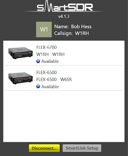
This is what the SmartSDR window looks like when two radios are available. When logging in, you simply click on the radio you want to use.
So that’s what’s been going on over the past year or two at my station. I should mention that one project that never got done was installing a brand new SteppIR DB-18. For several reasons, this antenna will probably never go up. If you have something like a C3 and a two element 40 meter beam and want to trade, let me know!
2026 should see the Antenna Genius switch installed but we also want to clean up the noise problem on the antennas close to the house. The biggest culprit seems to be an APC Smart UPS 1500 which generates a lot of noise. Also, the grounding is very limited and we have plans to fix that.
In the process of making a lot of these station changes, I pulled out all of the SO2R bandpass filters. This has put a dent in high-power SO2R but the antennas are spaced far enough apart so that a contest like NAQP, with low power, allows SO2R operation without interference. This will all be fixed in 2026.
Finally, the entire station – everything – will be rack mounted and installed in a corner of the garage. I’ll be building a new operating position with computers in front of me to control everything.
Schedule the time in your calendar to operate the contest. Get focused on making your best effort this year. Give the contest 100% effort for the time you have to operate.
I like to go to 3830 scores and copy my last year’s contest score and place it on the operating table so I can see how I did last year. This gives me a benchmark to beat.
In the California QSO Party, you need to be calling CQ all the time. People are looking for you; this is not the time to spend lots of time searching and pouncing. I wait about a second to a second and a half before my next CQ if no one answers me. Calling CQ is like fishing; if your line is not in the water, no fish will bite.
Keep your exchange to just the serial number and the county you’re in. You need to set the tempo of your exchange. If you sound like you mean business, they will respond in kind.
Plan your off times to be the most efficient so you’re not off when the rates are still high.
Our illustrious VP Steve NC6R was rooting around in his desk the other day and chanced upon a couple of thumb drives (remember those?) containing Contest and DX Academy presentations from the 2013 and 2014 International DX Convention (IDXC) in Visalia, CA.
Steve passed these along to your Editor to publish in The Nugget. And so, here they are for you enjoy and reminisce about contesting in the last decade! (And there’s a lot of still-relevant material!)
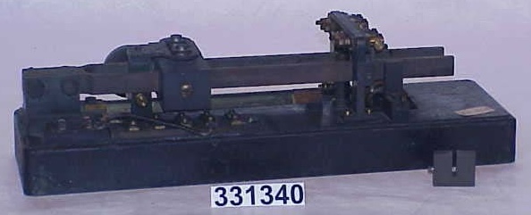
Terrestrial telegraphy required countless inventions, and one of the more unusual devices from that industry is the subject of this report. I am calling it a Telegraph Tuning Fork (TTF) because I can find no better description at this time. It came to me via a friend who got it from a fellow who collected surplus equipment, in particular from the Navy’s Mare Island facility near Vallejo, CA. Considering the history of the facility beginning in 1854 and the Navy’s extensive use of all forms of communication, this could indeed be the provenance of this item.
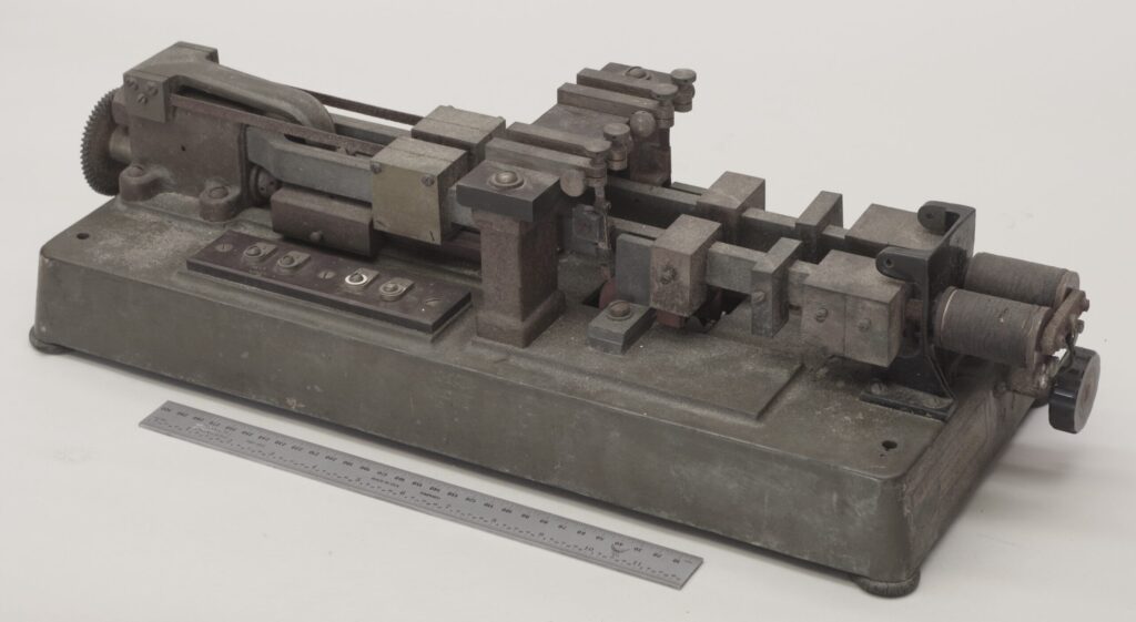
Figure 1. My mystery instrument.
Who Made It and When?
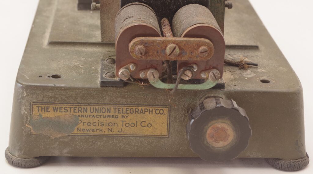
There is a partial label on the instrument, seen in Figure 2. It was made for The Western Union Telegraph Co., so indeed it has something to do with telegraphic communications. Its manufacturer turns out to be D. & H. Precision Tool Co. in Newark, NJ. This company was founded no later than 1918 by Mr. DeSaules and Mr. Hall, and still exists today as D & H Cutoff Co. So perhaps it was made in the early 20th century. Someone skilled at identifying early electrical components may have an opinion.
Figure 2. This label gives us a starting point.
Searching online, the closest match to my device was located at the Smithsonian (Figure 3). They identified it as a telegraph tuning fork, and the maker is Western Union Co. It does have some of the basic features and clearly we are on the right track for identification.
Figure 3. Photo from the Smithsonian National Museum of American History, identified as a telegraph tuning fork [Ref. 1].
Overview of the Instrument
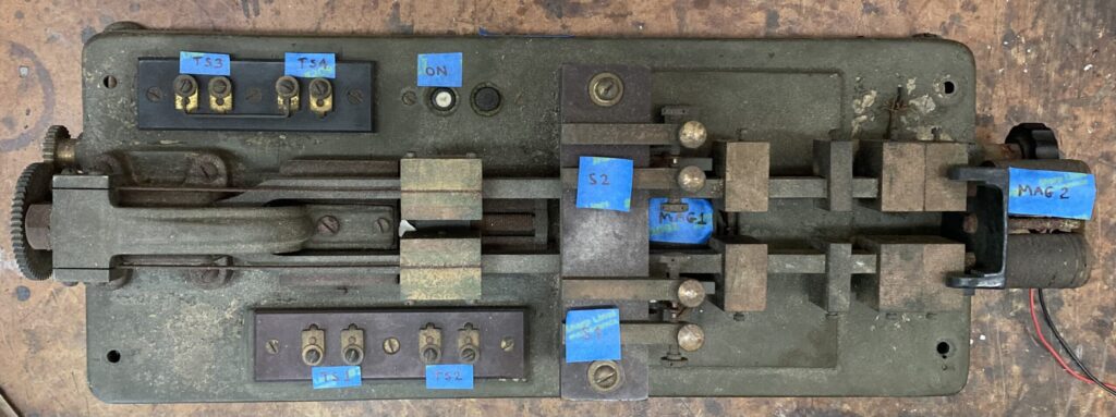
Figure 4 is an annotated top view that identifies the major components. The base is of cast bronze and the entire device weighs about 35 pounds. The main structure is literally a long, heavy tuning fork fabricated from steel and anchored at the left end. A series of weights adjust the resonant frequency. A large electromagnet (MAG-1) resides under the fork, with pole pieces just outside of the arms so that when energized the arms are pulled outward. Clearly this is the excitation method. Two sets of SPDT contacts are actuated by movement of the forks. At the far right end is a pair of coils (MAG-2A and B) that apparently are used to sense motion of the forks. Four terminal strips provide connection points.
A clever gear-driven mechanism slides tuning weights along the forks, thus allowing the resonant frequency to be adjusted while the forks are in motion. I located a patent [Ref. 2] “Adjustable-Vibration Tuning Fork” assigned to Western Union Telegraph Co. in 1923 that describes this mechanism. Due to age and corrosion, the mechanism is frozen, and no attempt was made to restore it.
Figure 4. Top view of the TTF, annotated.
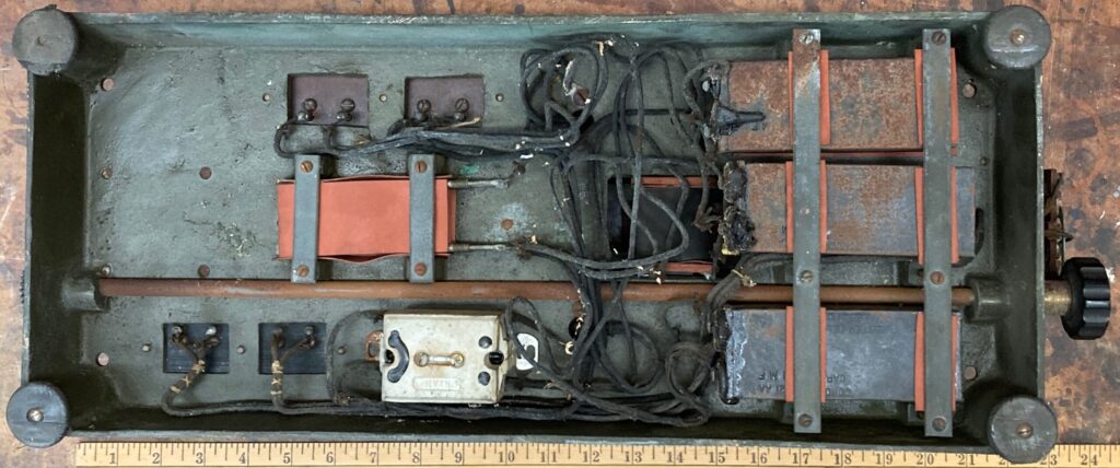
Looking at the bottom of the device in Figure 5, a number of electrical components are identified. Three identical capacitors, C1-C3, are all marked 1 uF and in fact tested good despite their age. A stack of three resistors, R1-3, measured 150 Ohms. A pushbutton module is connected in series with MAG-1, so that may be considered the on/off switch for excitation. I didn’t have a suitable instrument for measuring inductance but did measure the resistance of each coil.
Figure 5. Bottom view of the TTF, annotated.
Analysis and Operation
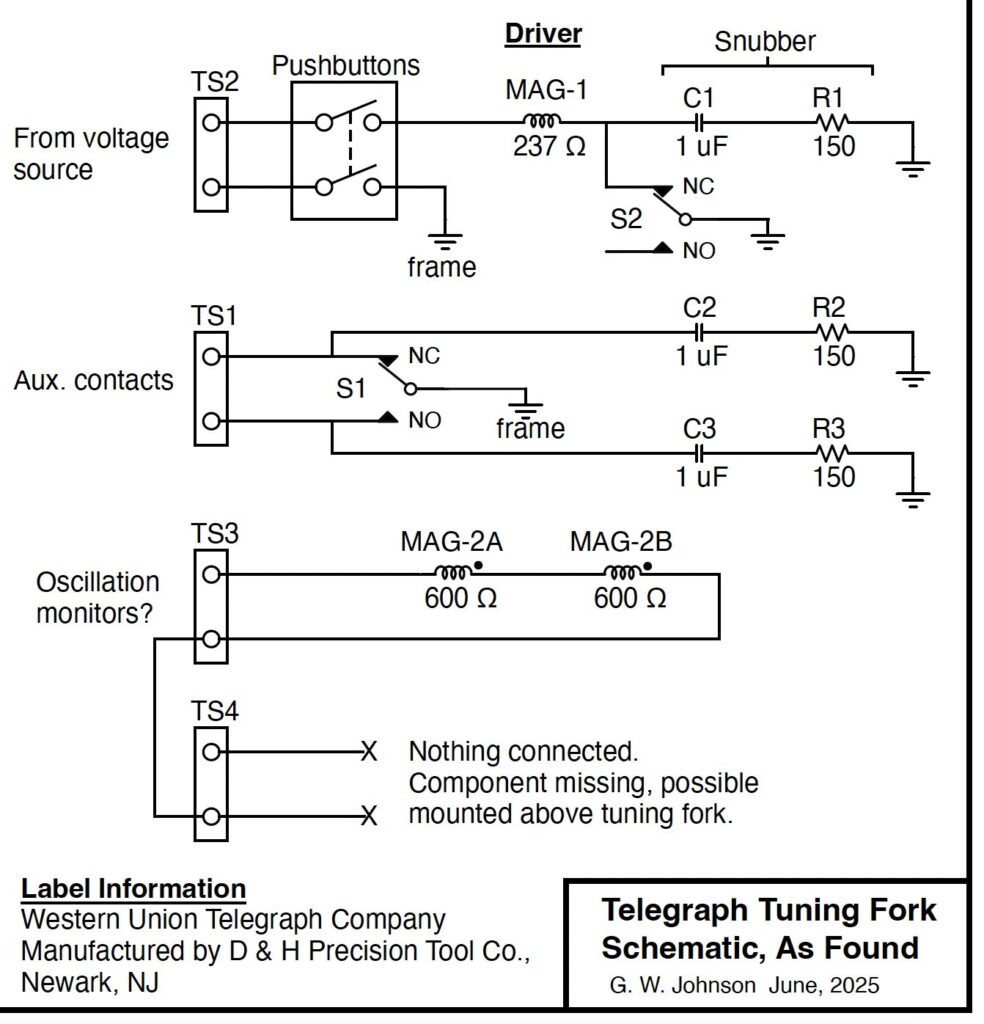
After identifying components and doing some wire tracing, a schematic was produced (Figure 6). Operation is simple. Starting at rest with S2 closed, an applied voltage produces a current in MAG-1, forcing the forks to move outward, which opens S2. Current collapses, allowing the forks to move inward, then the cycle repeats. This is a kind of relaxation oscillator and will preferentially operate at the resonant frequency of the mechanical system. C1 and R1 form a snubber circuit which suppresses arcing when the contacts open.
A second set of contacts, S1, also has snubber on each side and connections are simply routed to a terminal strip TS2. These could be used to synchronize an external device with the vibration of the forks.
Coils MAG-2A and B are connected in series and brought out to TS3. They could be used for monitoring oscillation. TS4 is routed to a pair of wires that are disconnected on this instrument. There are some mounting holes in a black bracket above MAG-2A and B that may have held a now-missing device.
Figure 6. Schematic diagram of the TTF. (Link to PDF)
Even after a hundred years or so, this instrument is still functional! Some cleaning of contacts at S2 and terminals at TS2 was all it required. Connecting a DC power supply and beginning at 40V, I slowly adjusted the contact spacing and the forks sprang to life, with a current draw of just 10 mA. With further adjustment, I found that the TTF would start and run as low as 3 V. Amplitude was roughly proportional to excitation voltage. Sitting on the bench, it made a low purring sound with no vibration felt in the base due to careful dynamic balancing of the forks.
Connecting MAG-2A and B to an oscilloscope, I observed oscillation at exactly 30 Hz. Considering the mass of the tuning forks, this should be a very stable oscillator, drifting only slowly with ambient temperature changes. Assuming the forks are made of ordinary steel, I estimate that the temperature coefficient of frequency is about -24 ppm/degC.
What is it For?
Little information on “telegraph tuning forks” can be located with a web search, but a number of interesting uses are suggested in a patent search. One fundamental application is synchronous telegraphy where the two ends of the connection rely on stable, matched oscillators to encode and decode transmitted data. More importantly, such synchronization allows multiplex telegraphy where several independent data streams may be sent down a single wired connection. In one patent [Ref. 3], a TTF is shown at each end of the link with its auxiliary contacts causing a large rotary switch to advance with each pulse. In effect, the rotary switch dynamically chooses among several sender-receiver pairs in a kind of time-sharing arrangement.
As time went on, manual sending and receiving of Morse code was sometimes replaced with faster automated transmission consisting of punched tape at the sending end and a variety of receiving devices. Synchronous timing is very important and once again the TTF appears. We would now call it a clock oscillator. By the way, these same mechanisms were also used for teletype data. Long terrestrial lines are problematic due to signal loss and distortion. What was needed is an amplifier of some sort, but that did not exist prior to the invention of the vacuum tube. So an electromechanical repeater was devised. The patent in Ref. 4 relies on synchronous telegraphy where the transmission occurs at a fixed frequency, and uses a TTF as a sampling device to pick out the best part of each signal pulse. The auxiliary contacts then produce a nice, clean output for retransmission.
This turns out to be an important and useful invention in the telegraph industry. Being a telegrapher myself (radio, to be exact), these devices are fascinating. If anyone has additional information about the TFF, I’d love to hear about it (email gwj@me.com). Additional high-resolution photos are available.
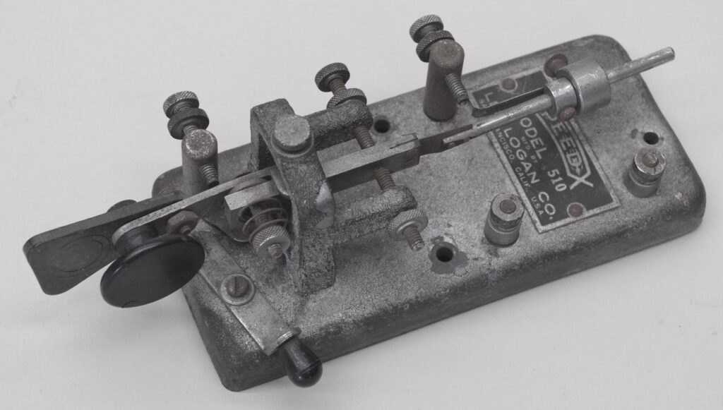
It seems that I spend too much time restoring old keys but somehow it’s more fun than trouble to me. I recently was given a beat-up and not very valuable Les Logan Speed-X model 510 bug.
This represents the low-end of the market in the 1930s, with a cast zinc base and all-steel components. It’s also too light and almost demands bolting to the table. As received, it was dirty and rusty, missing the damper assembly, the dot spring was broken, and an adjustment screw had its head broken off. Also there was no return spring. I stripped and repainted the base, cleaned everything, and machined the required parts. So this sow’s ear is… Well, still not a silk purse but at least it functions and is non-toxic. If you need any Morse key of any type repaired, let me know.
The Southern California Contest Club has announced that the Santa Maria 2026 DX & Contesters Convention is happening April 10-12, 2026 at The Historic Santa Maria Inn. Registration is open for the convention, and a Contest Dinner Friday night. Hotel reservations are also open.
Santa Maria is a charming town on the central coast, close to wineries and other attractions**.
** Your webmaster suggests making time for a visit to the nearby Carrizo Plain National Monument, where April is the start of the wildflower season, and the San Andreas Fault is visible in all its glory. Dirt road ready vehicles recommended. Also nearby are Hearst Castle and Pismo Beach.
We hams are famous for helping one another in many ways such as education, setting up equipment, or group operating events such as Field Day and emergency communications. Our team recently had a very successful experience helping a young CW op who was in need.
Twenty year old Jenna Hurley, N4JEH, is a blind student at the E.H. Gentry Facility, a component of the Alabama Institute for Deaf and Blind (AIDB). Adopted from an orphanage in China along with five siblings by her parents in Alabama, Jenna received excellent home schooling from her father, David. They even learned Braille together. David eventually discovered ham radio and started learning Morse code. That caught Jenna’s ear and together they used online resources to study and obtain their licenses when she was 17.
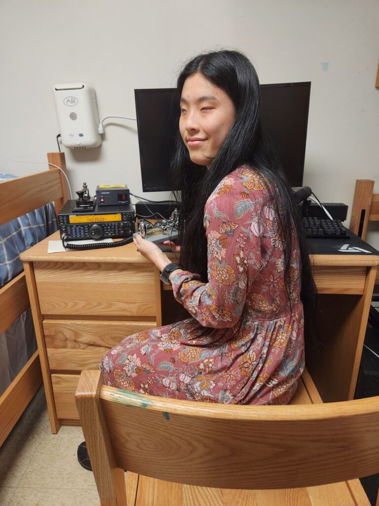
Jenna, N4JEH, showing off her new TS-590S and one of her favorite bugs. Photo credit: N4TMM.
They had a station set up at home, so Jenna was able to get on the air. CW was (and is) her passion and she quickly became highly skilled at it. So skilled and active in fact, that she was soon invited into both CWops and FOC, which is an honor for any telegrapher especially someone so new to the hobby. This led to numerous friendships worldwide.
After moving into the dorms at E.H. Gentry, Jenna was left without her own station to operate. With some difficulty due to poor blind accessibility, she was able to access some RemoteHams stations, and also did some POTA operating with her boyfriend, Gunner, KK7DEU. But every active ham really needs a proper station with a good radio and antenna. This is when those ham radio friendships really paid off.
There are many blind hams just like Jenna who may not be able to fully enjoy their hobby for various reasons, often financial. Gary, NA6O, started making friends with blind hams several years ago after realizing this need [Ref 1]. Specific radio models are of value to blind operators because they have a built-in voice guide and relatively easy-to-use controls. This is known as accessibility. The Kenwood TS-590S is perhaps the most accessible and popular. Gary started buying these radios on the second-hand market, outfitting them with the speech module, and then donating them to needy blind hams. One of his beneficiaries, Dave, W4CI (who is also an FOC member), mentioned that Jenna was a good candidate for a radio. That started the ball rolling.
Gary and Dave started working with Fred, KT5X (FOC of course!), who already knew Jenna, and in turn he recruited Jim, N4TMM, who turned out to be the key player in our success. Jim, who lives in Atlanta, would be in Sylacauga Alabama the first week of April to participate as a stone sculptor in the Alabama Marble Festival. Sylacauga is only a few miles down the road from Talladega, the location of E.H. Gentry and AIDB. So Jim was in perfect position to help set up Jenna’s station.
Jim approached the president of AIDB, Dr. Dennis Gilliam, and also Ms. Jessica Edmiston, who offered their full support. Meanwhile, Gary had sent Jim a power supply for the TS-590S that Dave was sending Jim. And Jim ordered a MyAntennas end fed halfwave wire antenna, a proven commercial design that will typically tune acceptably on several bands.
On Thursday, April 3rd, Jim met with EH Gentry maintenance people Joe Hutto, Don Llewellyn, and Tony Adams. Tony was there with his truck full of tools, ladders and other maintenance equipment, and Jim brought his radio toolbox and all the equipment for Jenna’s station that he had collected. After surveying the surroundings, Jim and Tony concluded that the best option was to lay the wire antenna, about 140 ft long, on the roof of the three-story dormitory where Jenna lives. So Tony got out his ladder and he and Jim installed the antenna on the roof and connected it to the radio in Jenna’s room. Thankfully they allowed a wall penetration for the coax, something that had been a concern for a long time.
At that point, Jim got on the phone with Gary, who was listening on his radio in California and also watching the Reverse Beacon network, gave feedback while Jim tuned and transmitted on various bands. The antenna and the station turned out to be excellent performers on 40 through 10 m, tuning fine and getting reports from NA as well as DX. The roof where the antenna is located is the highest point around, and the dorm is on a hill. The antenna lies generally in a Northeast to Southwest direction, and it propagates well in all directions. As a bonus, her noise floor is very low. We should all be so lucky in our modern age of rampant RFI.
In all of this, Jim was amazed and gratified at the support and assistance from AIDB and E.H. Gentry people in helping their student Jenna get on the air from her dorm and continue her excellent trajectory as a well-known CW operator. Jenna, in turn, takes great joy in operating from E.H. Gentry, thus adding to the fame and furthering the cause of this well known and highly regarded institute for the deaf and blind.
Jenna’s first contact with her new station was George, NE5A, who was also her advisor in the CWops CW Academy when she was starting out. A delightful coincidence! Since then, she’s been on the air every day, making contacts worldwide and is now a CWops advisor herself. And she is indeed a first-class operator, including QRQ, something that many hams only dream of achieving. Check out her YouTube channel, QRQ Maniacs [Ref 2.].
Jenna has a bright future ahead. She’s currently taking classes at Central Alabama Community College, focusing on computer science. She then plans to attend a university to obtain her BSCS degree, and has a particular interest in assistive technologies. Jenna wishes to thank some of her Elmers, particularly CWops advisors NE5A and AJ1DM, and her dad, David KO4WSU. We in the ham radio community are glad to have helped her along in some small way.
References
Gary Johnson, NA6O, “Summer’s Legacy.” Solid Copy, No… 177, October 2024. https://cwops.org/wp-content/uploads/2024/10/Solid-Copy_2024_October_FINAL.pdf
Here’s a few websites that I gleaned from DX Academy, Contest Academy, and Saturday presentations at the IDXC last weekend. Did I miss any? Add them in the comments! – Jeff WK6I
John NN6U presented “Contesting while activating POTA” (Parks On The Air). My takeaway is that, if you happen to be in a POTA park (like we often are during CQP for example), you can increase your visibility by operating as a POTA Activator. In particular, register your future activation on the POTA website, and when you go on the air you will get spotted there by POTA Hunters (and skimmers for CW/digital). This is not considered self-spotting. John said this presentation was basically the same as this one he made at the March 2024 NCCC meeting.
There were also presentations by Chris N6WM on Remote SO2R and 2BSIQ, and Hank W6SX on Having Fun Contesting.
A couple of websites from Bill K8TE’s “Tools for Propagation Prediction”. Here are some “Free DX Cluster Clients for Windows“. And Martti Laine’s book “Where Do We Go Next?” is available here to read for free.