by Norm Wilson N6JV – Visit the museum at N6JV.com
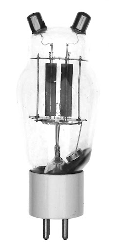
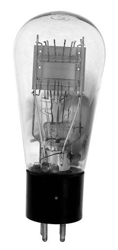
WE 220B
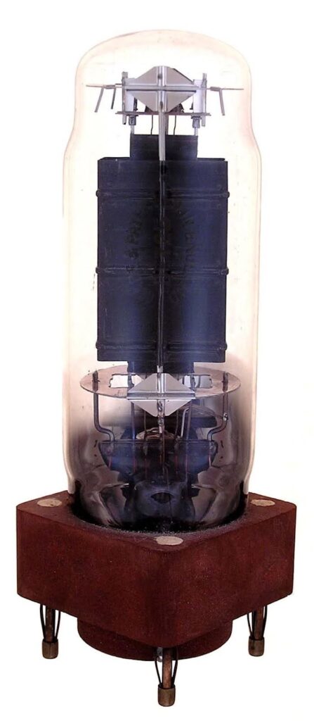
In the early 1920’s, Western Electric was legally allowed to sell new tubes to the civilian market. They also had some applications that would benefit their own company’s product line. One potential application was a very long-distance telephone system using 60 KHz. The tube that they were developing was a 10,000-watt dissipation, water cooled triode originally designated the 220A. When the tube was ready for sale it was named the 220B. This was the first commercially available water-cooled tube. The Navy designated it the CW1887 or the 38120. The tube was first used in Western Electric’s 5-B broadcast transmitter.
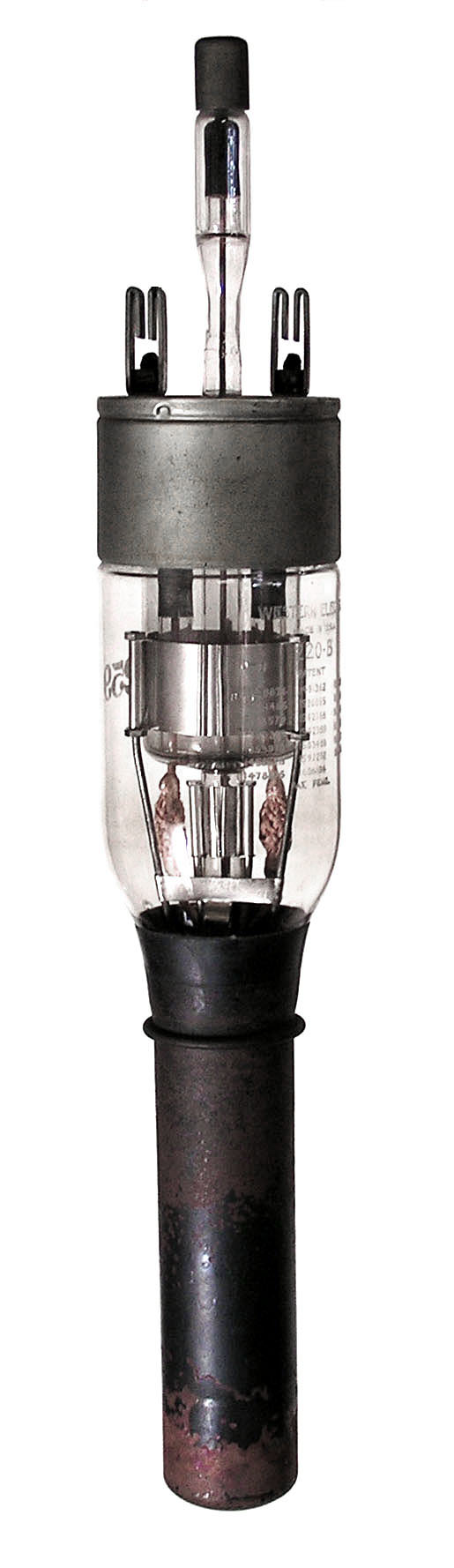
The WE 220B operated with up to 12,000 volts at 1.5 amps on the plate. The filament operated at 21.5 volts, AC at 41 amps. The amplification factor was 40 and could be operated at full power up to 3 MHz. The tube is 21.5 inches long including the strange grid connection that is on a stalk that is protruding from between the filament terminals. As a true believer in “Murphy’s Law”, especially the dropped part rule, I am amazed that any of these 100-year-old tubes have survived in one piece. That grid connection has a “hit me” sign on it. The 220B was quickly replaced by the WE 220C that had the grid rigidly out the side. This tube became the prototype for water cooled tube development for several decades.