by Gary Johnson, NA6O gwj@me.com
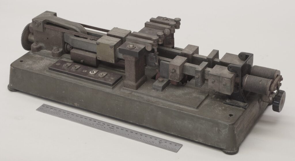
Terrestrial telegraphy required countless inventions, and one of the more unusual devices from that industry is the subject of this report. I am calling it a Telegraph Tuning Fork (TTF) because I can find no better description at this time. It came to me via a friend who got it from a fellow who collected surplus equipment, in particular from the Navy’s Mare Island facility near Vallejo, CA. Considering the history of the facility beginning in 1854 and the Navy’s extensive use of all forms of communication, this could indeed be the provenance of this item.
Who Made It and When?
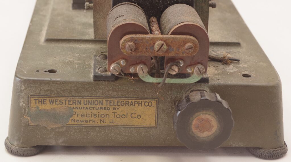
There is a partial label on the instrument, seen in Figure 2. It was made for The Western Union Telegraph Co., so indeed it has something to do with telegraphic communications. Its manufacturer turns out to be D. & H. Precision Tool Co. in Newark, NJ. This company was founded no later than 1918 by Mr. DeSaules and Mr. Hall, and still exists today as D & H Cutoff Co. So perhaps it was made in the early 20th century. Someone skilled at identifying early electrical components may have an opinion.
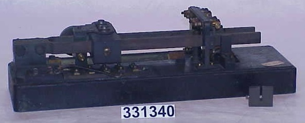
Searching online, the closest match to my device was located at the Smithsonian (Figure 3). They identified it as a telegraph tuning fork, and the maker is Western Union Co. It does have some of the basic features and clearly we are on the right track for identification.
Overview of the Instrument
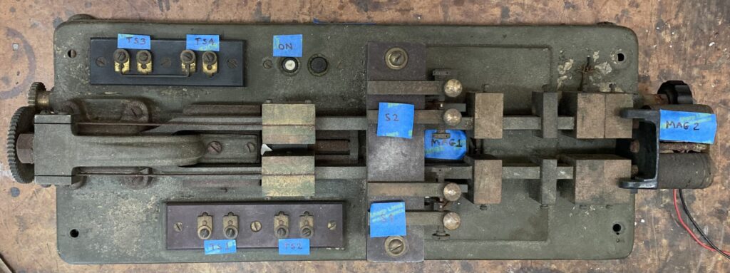
Figure 4 is an annotated top view that identifies the major components. The base is of cast bronze and the entire device weighs about 35 pounds. The main structure is literally a long, heavy tuning fork fabricated from steel and anchored at the left end. A series of weights adjust the resonant frequency. A large electromagnet (MAG-1) resides under the fork, with pole pieces just outside of the arms so that when energized the arms are pulled outward. Clearly this is the excitation method. Two sets of SPDT contacts are actuated by movement of the forks. At the far right end is a pair of coils (MAG-2A and B) that apparently are used to sense motion of the forks. Four terminal strips provide connection points.
A clever gear-driven mechanism slides tuning weights along the forks, thus allowing the resonant frequency to be adjusted while the forks are in motion. I located a patent [Ref. 2] “Adjustable-Vibration Tuning Fork” assigned to Western Union Telegraph Co. in 1923 that describes this mechanism. Due to age and corrosion, the mechanism is frozen, and no attempt was made to restore it.
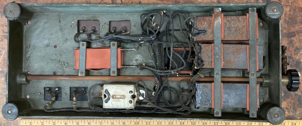
Looking at the bottom of the device in Figure 5, a number of electrical components are identified. Three identical capacitors, C1-C3, are all marked 1 uF and in fact tested good despite their age. A stack of three resistors, R1-3, measured 150 Ohms. A pushbutton module is connected in series with MAG-1, so that may be considered the on/off switch for excitation. I didn’t have a suitable instrument for measuring inductance but did measure the resistance of each coil.
Analysis and Operation
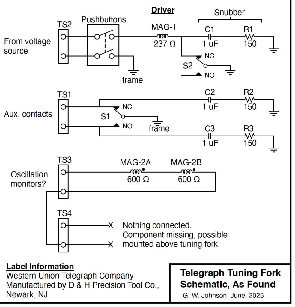
After identifying components and doing some wire tracing, a schematic was produced (Figure 6). Operation is simple. Starting at rest with S2 closed, an applied voltage produces a current in MAG-1, forcing the forks to move outward, which opens S2. Current collapses, allowing the forks to move inward, then the cycle repeats. This is a kind of relaxation oscillator and will preferentially operate at the resonant frequency of the mechanical system. C1 and R1 form a snubber circuit which suppresses arcing when the contacts open.
A second set of contacts, S1, also has snubber on each side and connections are simply routed to a terminal strip TS2. These could be used to synchronize an external device with the vibration of the forks.
Coils MAG-2A and B are connected in series and brought out to TS3. They could be used for monitoring oscillation. TS4 is routed to a pair of wires that are disconnected on this instrument. There are some mounting holes in a black bracket above MAG-2A and B that may have held a now-missing device.
Even after a hundred years or so, this instrument is still functional! Some cleaning of contacts at S2 and terminals at TS2 was all it required. Connecting a DC power supply and beginning at 40V, I slowly adjusted the contact spacing and the forks sprang to life, with a current draw of just 10 mA. With further adjustment, I found that the TTF would start and run as low as 3 V. Amplitude was roughly proportional to excitation voltage. Sitting on the bench, it made a low purring sound with no vibration felt in the base due to careful dynamic balancing of the forks.
Connecting MAG-2A and B to an oscilloscope, I observed oscillation at exactly 30 Hz. Considering the mass of the tuning forks, this should be a very stable oscillator, drifting only slowly with ambient temperature changes. Assuming the forks are made of ordinary steel, I estimate that the temperature coefficient of frequency is about -24 ppm/degC.
What is it For?
Little information on “telegraph tuning forks” can be located with a web search, but a number of interesting uses are suggested in a patent search. One fundamental application is synchronous telegraphy where the two ends of the connection rely on stable, matched oscillators to encode and decode transmitted data. More importantly, such synchronization allows multiplex telegraphy where several independent data streams may be sent down a single wired connection. In one patent [Ref. 3], a TTF is shown at each end of the link with its auxiliary contacts causing a large rotary switch to advance with each pulse. In effect, the rotary switch dynamically chooses among several sender-receiver pairs in a kind of time-sharing arrangement.
As time went on, manual sending and receiving of Morse code was sometimes replaced with faster automated transmission consisting of punched tape at the sending end and a variety of receiving devices. Synchronous timing is very important and once again the TTF appears. We would now call it a clock oscillator. By the way, these same mechanisms were also used for teletype data. Long terrestrial lines are problematic due to signal loss and distortion. What was needed is an amplifier of some sort, but that did not exist prior to the invention of the vacuum tube. So an electromechanical repeater was devised. The patent in Ref. 4 relies on synchronous telegraphy where the transmission occurs at a fixed frequency, and uses a TTF as a sampling device to pick out the best part of each signal pulse. The auxiliary contacts then produce a nice, clean output for retransmission.
This turns out to be an important and useful invention in the telegraph industry. Being a telegrapher myself (radio, to be exact), these devices are fascinating. If anyone has additional information about the TFF, I’d love to hear about it (email gwj@me.com). Additional high-resolution photos are available.
References
- National Museum of American History, “Telegraph tuning fork”, Cat. No. 331340. https://americanhistory.si.edu/collections/object/nmah_890715
- Walter A. Houghtaling, “Adjustable-Vibration Tuning Fork”, U.S. Patent No. 1,466,623, 1923.
- Poul La Cour, “Synchronous Telegraphy”, U.S. Patent No. 302,502, 1884.
- Herbert Angel, “Regenerative Telegraph Repeater”, U.S. Patent No. 1,673,726, 1928.